
Leadthrough element

a technology of lead through and ring, which is applied in the direction of insulating bodies, basic electric elements, multi-purpose tools, etc., can solve the problems of poor protection of the loom of cables against mechanical loads, unsuitable system for routing a line, and unsuitability of such a large press in narrow and angular installation spaces, etc., to achieve simple processing, reduce production costs, and ensure connection.

Inactive Publication Date: 2007-08-28
AIRBUS OPERATIONS GMBH
View PDF17 Cites 11 Cited by
  • Summary
  • Abstract
  • Description
  • Claims
  • Application Information

AI Technical Summary

Benefits of technology

The present invention provides a leadthrough element for waterproof and airtight leadthrough of lines in various applications. The leadthrough element has one or several recesses for leading the lines through, which are designed to protect the lines from mechanical loads and ensure a permanent seal. The leadthrough element can be easily installed and replaced, and it allows for the lines to be fed through in opposite directions. The leadthrough element is particularly useful in situations where the lines have to be protected against mechanical loads, such as in floor channels or cable ducts. The leadthrough element can be made with an adhesive to ensure a tight and secure seal with the lines. The leadthrough element can be compressed during installation to provide a seal with contact areas on the recesses. The leadthrough element can be designed with projections and recesses to prevent slipping and ensure a safe connection.

Problems solved by technology

While this results in a largely waterproof connection between the line system and the sealing element, however, the line system, which comprises a multitude of conductors, leaves the sealing element essentially perpendicularly.
This can be disadvantageous in particular in cases where the sealing element has been built into a floor panel, because as a result of exiting perpendicularly, the loom of cables is poorly protected against mechanical loads which frequently occur in particular in the floor area of a highly frequented space.
If, as in the specific case, a line has to be placed flat along the floor in a duct after having been fed-through perpendicularly, the system shown is also not suitable for routing a line because the tail of the cable juts out perpendicularly from the floor.
Furthermore, the described sealing element is associated with a disadvantage in that the line system is connected to the sealing element by means of a large press.
However, the use of such a large press is unsuitable in narrow and angular installation spaces in which a sealing cable leadthrough is to be used.
In particular, when retrofitting already existing line systems or looms of cables with a waterproof cable leadthrough, the aforementioned press tool has to be available—a factor which represents a considerable additional expense from the point of view of both logistics and finance.
These known methods for sealing line leadthroughs by means of extrusion coating the lines by embedding in foam or in gel may be associated with a disadvantage in that, in particular with the use of molten casting resins, heat protection must be provided for the lines.
Furthermore, closing a hole by means of a gel or the like requires the presence of a type of carrier plate in the aperture, since otherwise the sealing compound would be injected into empty space and would fail to fulfill the required purpose.
However, the implementation of this method is labour intensive and time consuming.

Method used


Image

  • Leadthrough element
  • Leadthrough element
  • Leadthrough element

Examples


Embodiment Construction

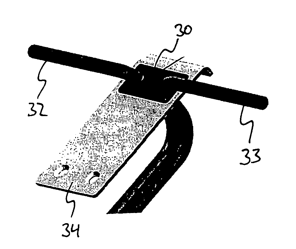
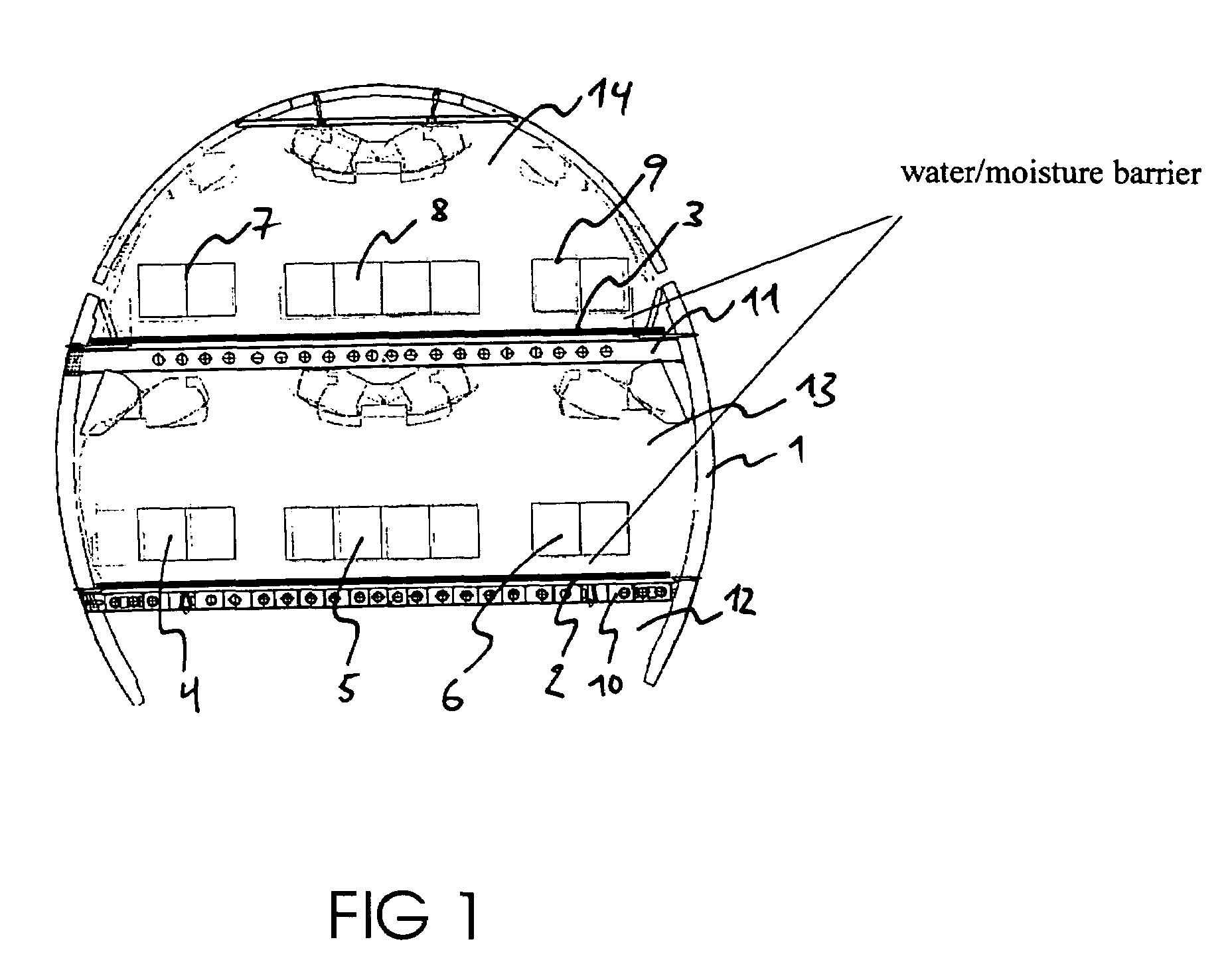
[0029]FIG. 1 shows a diagrammatic cross-sectional view of an aircraft. Essentially, the fuselage of the aircraft comprises a skin 1 which shields the interior of the aircraft from the exterior air. The transverse and longitudinal bracing 10, 11 not only serves to provide stability, but also to accommodate the passenger seats 4, 5, 6, 7, 8 and 9. Furthermore, numerous lines, both electrical and other lines, are routed in said transverse and longitudinal bracing 10, 11. The other lines can for example be coolant lines or hydraulics lines. Furthermore, lines for the supply of water or for guiding mechanical elements such as for example Bowden wires for mechanical control of e.g. the elevator or rudder are imaginable. This bracing 10, 11 is covered with floor panels 2, 3 which comprise a water barrier or moisture barrier. Furthermore, it is imaginable that the floor panels abut against each other and against the skin 1 of the aircraft so as to provide an airtight seal, so that various c...


PUM

PropertyMeasurementUnit
pressureaaaaaaaaaa
contact areaaaaaaaaaaa
depthaaaaaaaaaa

Abstract

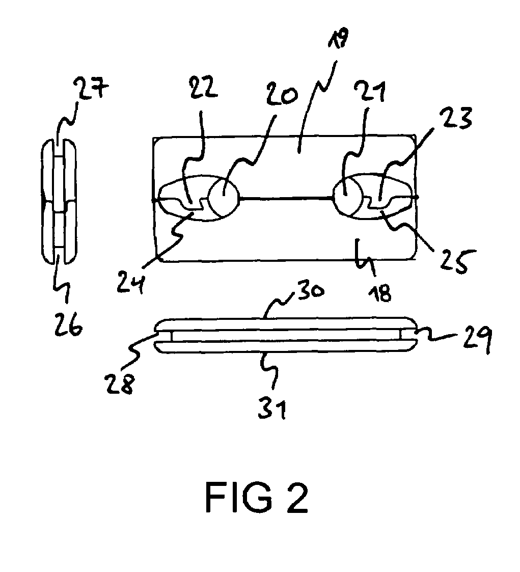
Leadthrough elements for waterproof or airtight leading through of one or several lines are often associated with a disadvantage in that the led-through lines are routed largely without protection, and in that the tight seal between the leadthrough element and the line deteriorates in the course of mechanical loads being exerted on the lines. According to one embodiment of the present invention, a leadthrough element is provided in which each line exits in such a way from the top of the leadthrough element that the line after exiting runs flat along the top of the leadthrough element. By integrating this leadthrough element in a floor panel of an aircraft, in particular an Airbus A380, an advantageous seal of the line leadthrough is ensured, wherein the leadthrough element protects the line against increased mechanical loads, and thus ensures a permanent seal of the line leadthrough, with said seal meeting the quality requirements of the aircraft industry even in the case of increased mechanical loads.

Description

FIELD OF THE INVENTION[0001]The present invention relates to a leadthrough element for leading lines through. In particular, the present invention relates to a leadthrough element for leading one or more lines through, e.g. a wall of a structure, in a waterproof manner.TECHNOLOGICAL BACKGROUND OF THE INVENTION[0002]Generally speaking, such leadthrough elements are affixed to a wall of a control cabinet, a dividing wall, a floor panel or the like. Affixing the leadthrough element to the wall generally speaking takes place by clamping, screwing or gluing.[0003]From DE 19640816 a sealing element for multi-conductor line systems which are embedded in adhesive tape is known, wherein sealing between the sealing element and the line systems takes place in that the line system, which comprises the adhesive tape, is fed through the sealing element and is compressed by said sealing element such that even pressure is exerted onto the line system, and the line system is pressed against the inte...

Claims


Application Information

Patent Timeline
Patent Type & Authority Patents(United States)
IPC IPC(8): H02G3/18H01B17/30H02G3/22
CPCH02G3/22H01B17/30Y10T16/063Y10T16/05
Inventor ICKERT, MICHAEL
Owner AIRBUS OPERATIONS GMBH
Learn More