Micro-oscillation element incorporating springs

a micro-oscillation element and spring technology, applied in the field of micro-oscillation elements, can solve the problems of difficult to implement high flatness on the entire mirror face over a wide area, the mirror face tends to warp, and the flatness of the mirror face which reflects light is high, so as to prevent the deformation of the oscillation section in the oscillation direction, the rotational rigidity is high, and the thinness is sufficient.

Inactive Publication Date: 2007-08-28
FUJITSU LTD
View PDF29 Cites 9 Cited by
  • Summary
  • Abstract
  • Description
  • Claims
  • Application Information

AI Technical Summary

Benefits of technology

[0019]In the micro-oscillation element having the above configuration, the rotational rigidity of the oscillation section can be acquired by the first and second springs, which deflect along with the oscillation operation of the oscillation section. This is because the first and second springs apply the deflection resistance, generated by the deflection rigidity and flexural rigidity, to the oscillation operation of the oscillation section respectively. This is physically equivalent to a torsion bar applying the torsional resistance, generated by the torsional rigidity, to the oscillation operation when a torsion bar, which connects the oscillation section and the frame and which defines the oscillation axis in the oscillation operation of the oscillation section, exists. Therefore in the micro-oscillation element according to the first aspect of the present invention, it is possible to acquire a desired high rotational rigidity for the oscillation section by appropriately adjusting the deflection rigidity of the first and second springs. This element can also be constructed such that the oscillation section appropriately oscillates without using a torsion bar which connects the oscillation section and frame.
[0035]The above configuration of the micro-oscillation element corresponds to the configuration where the abovementioned second frame, the third spring and the fourth spring are added to the micro-oscillation element according to the first aspect of the present invention. Therefore according to the above arrangement, a high rotational rigidity can be acquired and a small moment of inertia can be implemented for the oscillation main section, just like the oscillation section in the first aspect. In addition, a high rotational rigidity can be acquired and a small moment of inertia can be implemented for the main frame, just like the abovementioned oscillation section in the first aspect. In this way, the micro-oscillation element according to the first aspect of the present invention can be constructed as a multi-axis micro-oscillation element.

Problems solved by technology

One technical issue which is required for micro-mirror element is the high flatness of the mirror face which reflects light.
However, according to surface micro-machining technology, where a mirror face to be finally created is thin, the mirror face tends to warp, and it is difficult to implement high flatness on the entire mirror face over a wide area.
However, as the mirror section 61 becomes thinner, the mirror section 61 itself tends to deflect, and assuring the flatness of the mirror face 64 tends to become difficult.
In this way, prior art has difficulty to operate a micro-mirror element or a micro-oscillation element at a high resonance frequency.

Method used


Image

  • Micro-oscillation element incorporating springs
  • Micro-oscillation element incorporating springs
  • Micro-oscillation element incorporating springs

Examples


first embodiment

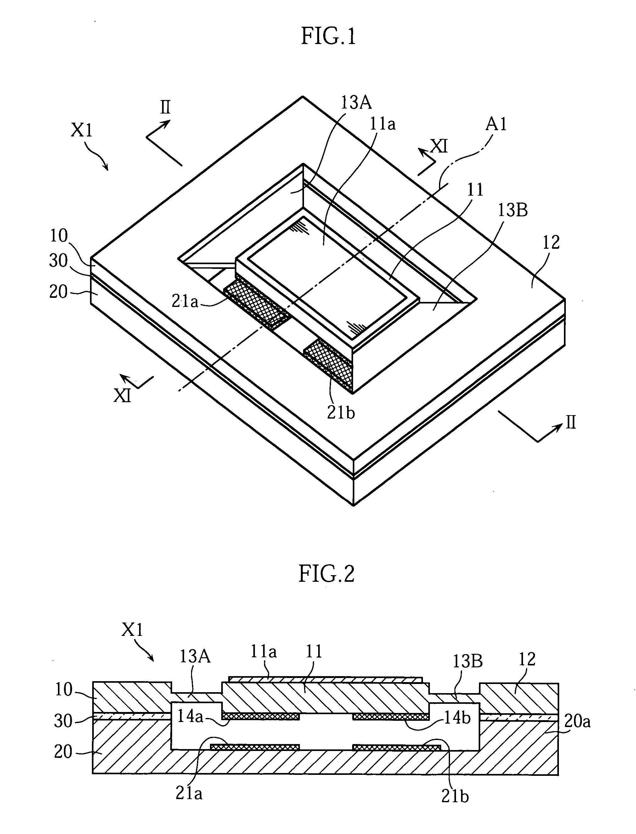
[0063]FIG. 1 and FIG. 2 show the micro-mirror element X1 of the present invention. FIG. 1 is a perspective view of the micro-mirror element X1, and FIG. 2 is a cross-sectional view along the II-II line in FIG. 1. The micro-mirror element X1 has a structure where the mirror substrate 10 and the base substrate 20 are layered via the insulation layer 30.

[0064]The mirror substrate 10 is comprised of a mirror section 11, a frame 12 surrounding this, and a pair of springs 13A and 13B which connect the mirror section 11 and the frame 12. The mirror substrate 10 is formed by bulk micro-machining technology, from a silicon substrate to which conductivity is provided by doping such n-type impurities as P and As, or by such a P-type impurity as B. Specifically, the mirror section 11, the frame 12 and the pair of springs 13A and 13B are formed on a plate type conductive silicon substrate by dry etching or by wet etching, which is performed using a mask for patterning. For the dry etching, Deep ...

second embodiment

[0082]FIG. 12 to FIG. 14 show a micro-mirror element X2 according to the present invention. FIG. 12 is a perspective view of the micro-mirror element X2. FIG. 13 is a cross-sectional view along the XIII-XIII line in FIG. 12, and FIG. 14 is a cross-sectional view along the XIV-XIV line in FIG. 12. The micro-mirror element X2 has a structure where the mirror substrate 10 and the base substrate 20 are layered via the insulation layer 30, and the mirror substrate 10 is comprised of a mirror section 11, a frame 12, a pair of springs 13A and 13B, and a pair of torsion bars 15. The difference from the micro-mirror element X1 is that the micro-mirror element X2 has a pair of torsion bars 15, and the rest of the configuration and variant forms thereof are the same as the micro-mirror element X1.

[0083]The pair of torsion bars are connected to the mirror section 11 and the frame 12, and defines the oscillation axis A2 in the oscillation operation of the mirror section 11. Each one of the torsi...

third embodiment

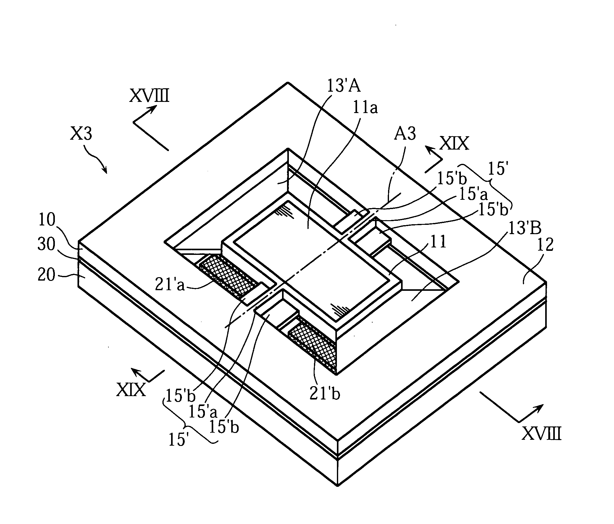
[0089]FIG. 17 to FIG. 19 show the micro-mirror element X3 according to the present invention. FIG. 17 is a perspective view of the micro-mirror element X3. FIG. 18 is a cross-sectional view along the XVIII-XVIII line in FIG. 17, and FIG. 19 is a cross-sectional view along the XIX-XIX line in FIG. 17. The micro-mirror element X3 has a structure where the mirror substrate 10 and the base substrate 20 are layered via the insulation layer 30, and the mirror substrate 10 is comprised of a mirror section 11, a frame 12, a pair of springs 13′A and 13′B, and a pair of torsion bars 15′. In the mirror substrate 10, movable electrodes 14′a and 14′b are disposed, and in the base substrate 20, fixed electrodes 21′a and 21′b are disposed. The difference from the micro-mirror element X2 is that the micro-mirror element X3 is comprised of the springs 13′A and 13′B, movable electrodes 14′a and 14′b, fixed electrodes 21′a and 21′b, and a pair of torsion bars 15′, instead of the springs 13A and 13B, m...


PUM


Abstract

A micro-oscillation element includes an oscillation section and a frame. The oscillation section is provided with a mirror surface and is connected to the frame via trapezoidal first and second springs. The oscillation section is located between the first spring and the second spring. Each of the first spring and the second spring is deformable along with the oscillation of the oscillation section.

Description

BACKGROUND OF THE INVENTION[0001]1. Field of the Invention[0002]The present invention relates to a micro-oscillation element that has an oscillating section for which rotary displacement is possible. More particularly, the present invention relates to a micro-oscillation element which can be applied to a micro-mirror element, which is built into such optical devices as optical measurement devices for performing precision measurement using light waves, optical disk devices for recording and reproducing data for optical disks, and optical switching devices for switching the optical paths between a plurality of optical fibers, so as to change the traveling direction of the light.[0003]2. Description of the Related Art[0004]Recently the application of MEMS (Micro-Electro-Mechanical-System) devices, which have a microstructure created by micro-machining technology, are being attempted in various technical fields. For example, in the field of optical communication technology, micro-mirror...

Claims


Application Information

Patent Timeline
Patent Type & Authority Patents(United States)
IPC IPC(8): H02N1/00G02B26/10G02B26/08H04N1/028H04N1/036
CPCG02B26/0841A47K3/28
Inventor XIAOYU, MIUEDA, SATOSHIOKUDA, HISAOTSUBOI, OSAMUSONEDA, HIROMITSUKOUMA, NORINAOSAWAKI, IPPEINAKAMURA, YOSHITAKA
Owner FUJITSU LTD
Why Eureka
Try Eureka