Efficient fast pulsed laser or light-emitting diode driver

a laser or light-emitting diode technology, applied in semiconductor lasers, process and machine control, instruments, etc., can solve the problems of inefficient use of linear current sources, inefficient analog current sources, and difficult to switch off and on from zero

Active Publication Date: 2007-08-28
ANALOG MODULES
View PDF11 Cites 24 Cited by
  • Summary
  • Abstract
  • Description
  • Claims
  • Application Information

AI Technical Summary

Problems solved by technology

Using a linear current source is inefficient because voltage is dropped across the linear pass element, or shunt element as shown in commonly-owned U.S. Pat. No. 6,587,490.
Turning a single phase switching power supply off and on from zero is problematical because the control loop bandwidth limits the potential switching speed.
Such analog current sources are inefficient due to power (e.g., heat) dissipation in the linear pass element controlling the current.

Method used


Image

  • Efficient fast pulsed laser or light-emitting diode driver
  • Efficient fast pulsed laser or light-emitting diode driver

Examples


Embodiment Construction

[0022]The invention is a pulsed current driver for driving current-driven devices (loads) such as light emitting diodes (LEDs) or laser diodes.

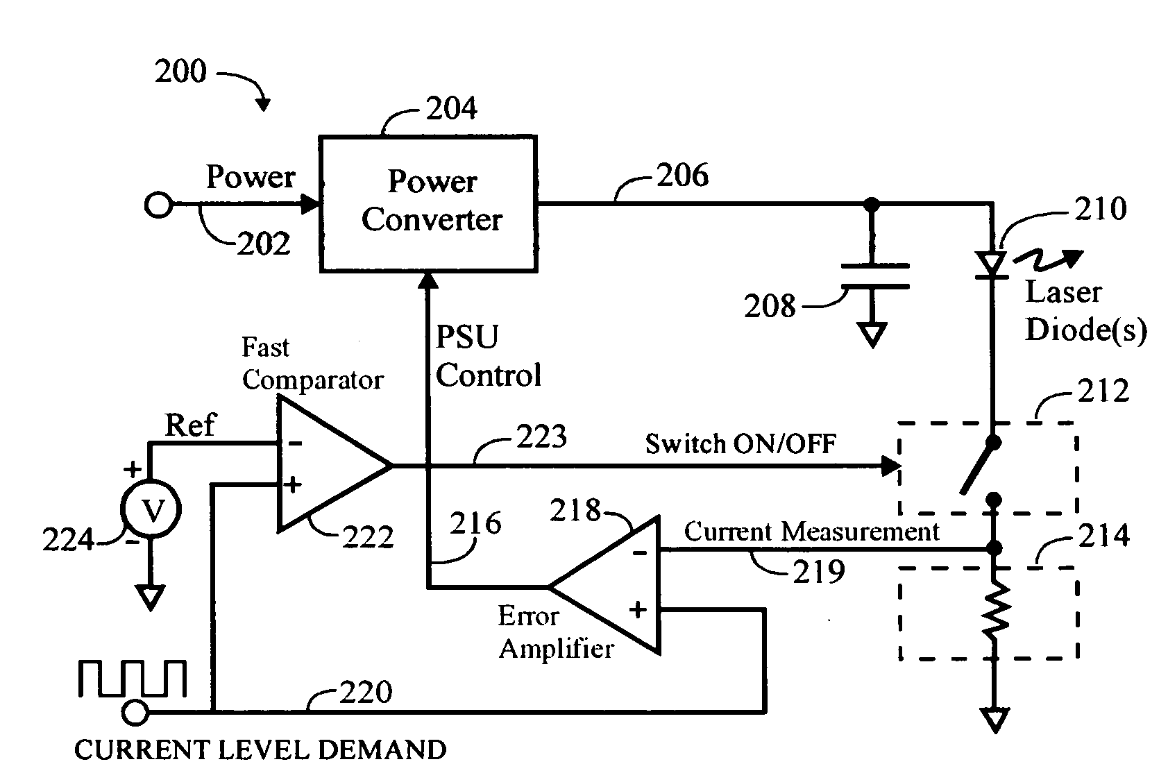
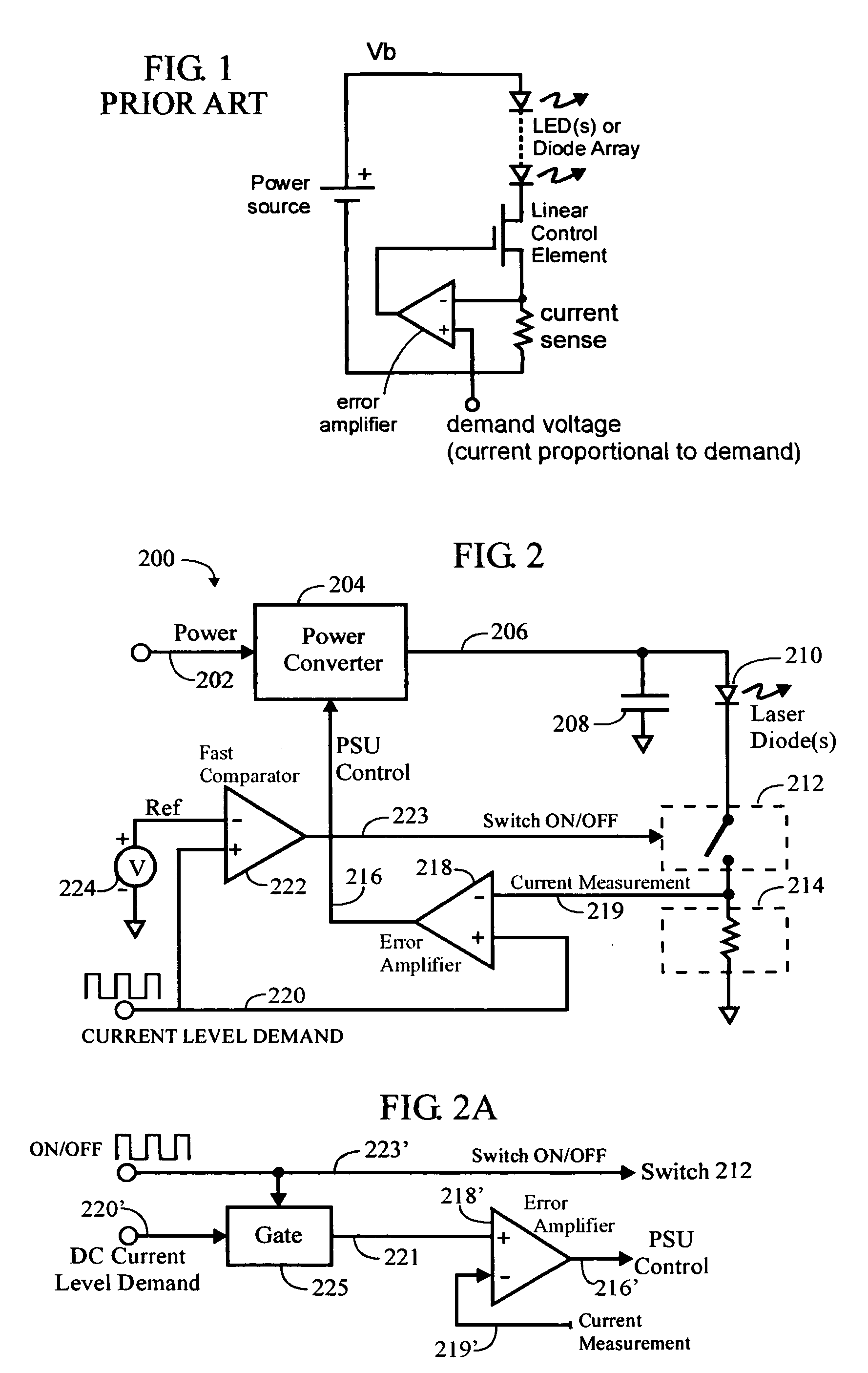
[0023]FIG. 2 is a schematic diagram of an embodiment of a pulsed current driver 200 of the present invention. Power is provided on an input line 202 to a power converter 204. The power converter is also referred to as a power supply unit, or “PSU”.

[0024]The power converter 202 would normally be supplied with DC (direct current) voltage, but it could also rectify AC (alternating current) into the DC voltage needed, then use preferably multiple phases to generate the current for the load with fast control response.

[0025]The output of the PSU 204 is provided on a line 206 to an output filter (reservoir) capacitor 208, and to an end (e.g., anode) of a laser diode or light-emitting diode 210, or an array of such diodes or similar light emitting current fed device with a positive resistance. The other end (e.g., cathode) of the laser or LED 210 is ...


PUM


Abstract

A capacitor is connected to the output of a multiphase power converter, and a current-driven device (e.g., LED or laser diode) is also connected to the power converter output. A solid state switch (FET or IGBT) is connected in series with the current-driven device. Means are provided for sensing current through the current-driven device. An error amplifier compares sensed current through the current-driven device with a current level demand signal and controls the output of the power converter. Means are provided for turning the switch on and off and may be (i) a fast comparator receiving a voltage reference signal at one input and the current level demand signal at another input, and outputting the switch on / off signal to the switch or (ii) an externally-generated logic signal provided directly to the switch.

Description

CROSS-REFERENCE(S) TO RELATED APPLICATION(S)[0001]This application claims priority to U.S. Provisional Patent Application No. 60 / 545,789 filed Feb. 19, 2004 (Crawford, Morales).[0002]This application is also a continuation-in-part of U.S. patent application Ser. No. 10 / 889,308 filed Jul. 12, 2004 (Crawford, Harwick, Morales), which is a non-provisional application claiming priority to U.S. Provisional Patent Application No. 60 / 578,667 filed Jun. 9, 2004.TECHNICAL FIELD OF THE INVENTION[0003]The invention relates to pulsed current drivers for driving current-driven devices (loads) such as light emitting diodes (LEDs) or laser diodes.BACKGROUND OF THE INVENTION[0004]Pulsed laser or LED diode drivers are used to generate pulses of current, typically into a series array of lasing diodes. The light output is used for various purposes, such as pumping lasers, or timed illumination. The driver design typically comprises a storage capacitor, the laser diode array, and a pulsed current sourc...

Claims


Application Information

Patent Timeline
Patent Type & Authority Patents(United States)
IPC IPC(8): G05F1/59H01S5/042H01S5/068H02M3/335H05B44/00
CPCH05B33/0818H01S5/0428H01S5/06808H05B45/37
Inventor CRAWFORD, IAN D.MORALES, MIGUEL
Owner ANALOG MODULES
Why Eureka
Try Eureka