Method and apparatus for catheter navigation and location and mapping in the heart

a catheter navigation and catheter positioning technology, applied in the computer-based medical system field, can solve problems such as errors in position or electrode location

Inactive Publication Date: 2007-08-28
ST JUDE MEDICAL ATRIAL FIBRILLATION DIV
View PDF99 Cites 1196 Cited by
  • Summary
  • Abstract
  • Description
  • Claims
  • Application Information

AI Technical Summary

Benefits of technology

[0018]The improved location methodologies allow for the collection of location data from one or more catheter electrodes all during the heart contraction cycle and

Problems solved by technology

Although the Wittkampf system is both safe and effective there are several

Method used


Image

  • Method and apparatus for catheter navigation and location and mapping in the heart
  • Method and apparatus for catheter navigation and location and mapping in the heart
  • Method and apparatus for catheter navigation and location and mapping in the heart

Examples


Embodiment Construction

System Level Overview and Basic Location Methodology

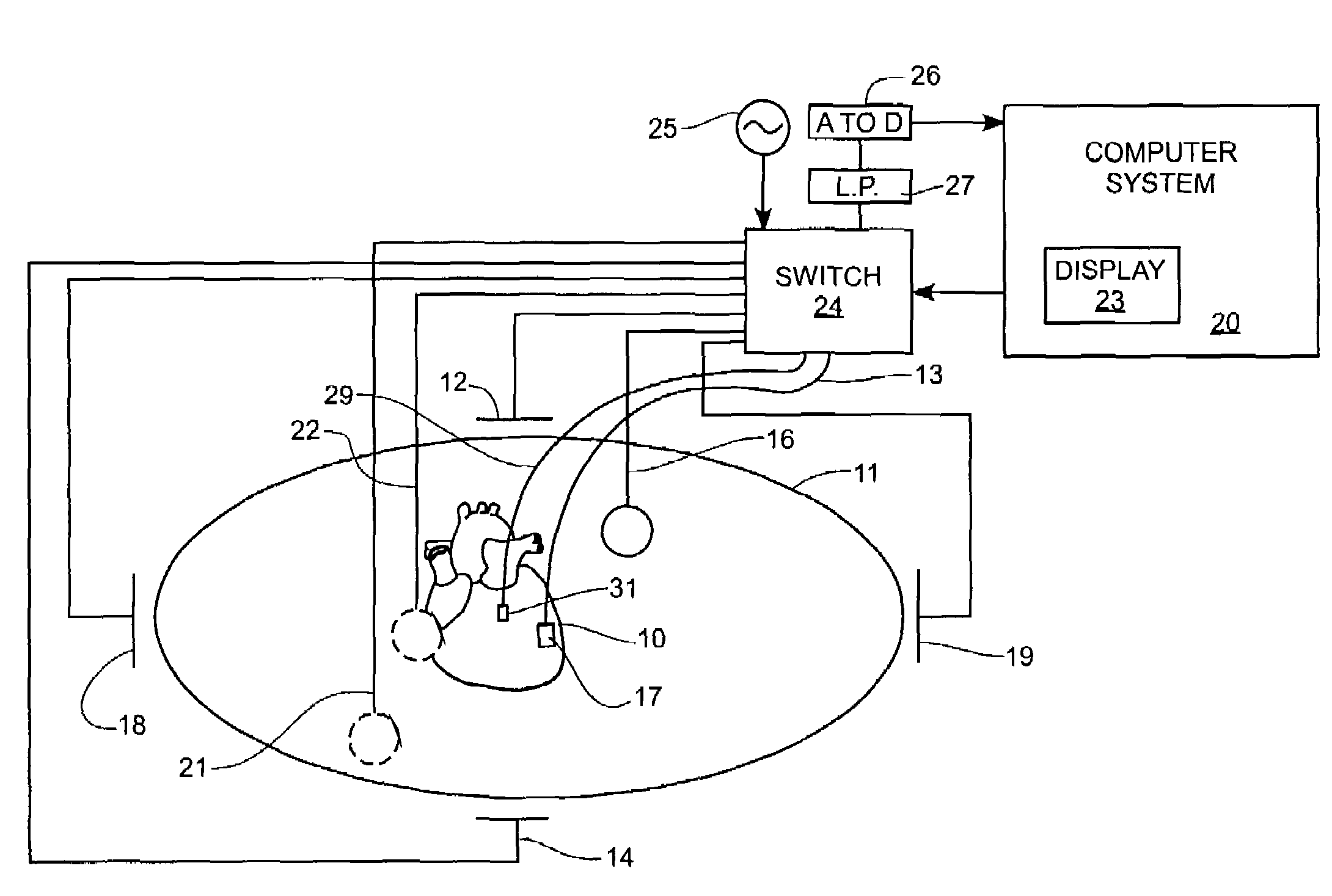
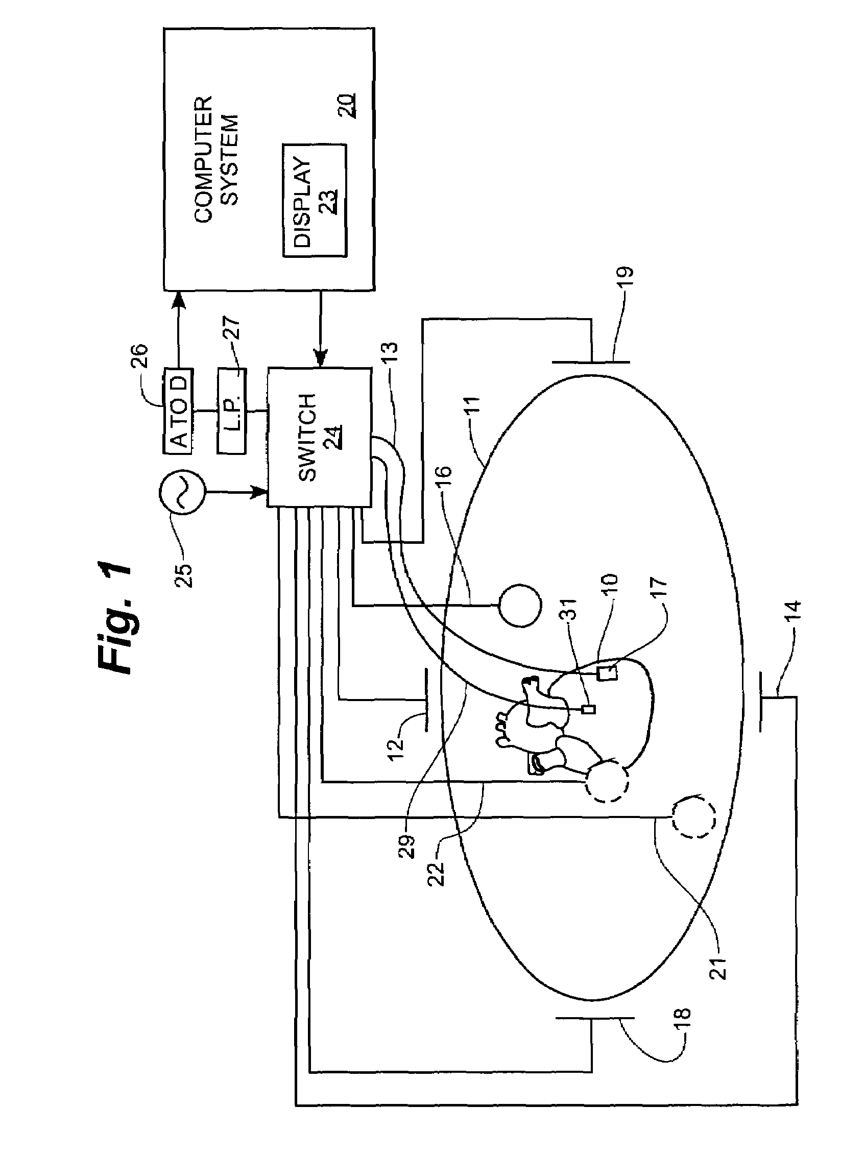
[0034]FIG. 1 shows a system level diagram in schematic form. The patient 11 is depicted as an oval for clarity. Three sets of surface electrodes are shown as 18,19 along a Y-axis; as 12,14 along an X-axis; and 16, 22 along a Z-axis. Patch electrode 16 is shown on the surface closest the observer and patch 22 is shown in outline form to show the placement on the back of patient 11. An additional patch electrode called a “belly” patch is also seen in the figure as patch electrode 21. Each patch electrode is independently connected to a multiplex switch 24. The heart 10 lies between these various sets of patch electrodes. Also seen in this figure is a representative catheter 13 having a single distal electrode 17 for clarity. This distal electrode 17 is called the “roving electrode” or “measurement electrode” throughout the specification. Typically multiple electrodes on each catheter will be used. A fixed reference electrode 31 attac...


PUM


Abstract

A medical system for finding and displaying the location of electrodes within the body. The electrodes may be used to measure the voltage on the heart wall and display this as an activation map on a geometry representing the heart chamber.

Description

CROSS-REFERENCE TO RELATED CASES[0001]The present application claims the benefit of U.S. Provisional Patent Application 60 / 461,004 filed Apr. 7, 2003, which is incorporated by reference herein. The present Application is also a Continuation in Part of U.S. patent application Ser. No. 09 / 107,371 filed Jun. 30, 1998. Each application is incorporated by reference in its entirety herein.FIELD OF THE INVENTION[0002]The present invention relates generally to a computer based medical system that can be used to position and navigate electrophysiology catheters and ablation catheters inside the heart of a patient. The catheters are used to create an image of the interior of the heart, and electrophysiology information collected from the catheters is presented to a physician user to guide a therapy or diagnosis.BACKGROUND OF THE INVENTION[0003]Wittkampf in his U.S. Pat. Nos. 5,697,377 and 5,983,126, discloses a system for determining the position or location of a catheter in the heart. These ...

Claims


Application Information

Patent Timeline
IPC IPC(8): A61B5/042A61B5/107A61N1/362A61N1/37
CPCA61B5/0422A61B5/06A61B5/1076A61B5/7207A61N1/3625A61N1/3702A61B2019/5253A61B2562/0209A61B2562/046A61B2019/5272A61B5/065A61B2034/2053A61B2034/2072A61B5/287
Inventor HAUCK, JOHN A.SCHWEITZER, JEFF A.CRAVEN, MICHAELAFONSO, VALTINOCOTNER, HOLLYCALLAGHAN, FRANKSCHULTZ, JOHN
Owner ST JUDE MEDICAL ATRIAL FIBRILLATION DIV
Why Eureka
Try Eureka