Computer device to calculate emission control device functionality

a technology of emission control device and computer device, which is applied in the direction of hydrodynamic testing, instruments, machines/engines, etc., can solve the problems of platinum surface area loss, platinum performance typically degrades, and the activity of the catalyst used to form solid nitrate, etc., and achieves less carbon dioxide and less fuel.

Inactive Publication Date: 2007-08-28
FORD GLOBAL TECH LLC
View PDF33 Cites 19 Cited by
  • Summary
  • Abstract
  • Description
  • Claims
  • Application Information

AI Technical Summary

Benefits of technology

[0002]Lean-burn gasoline engines can be more efficient and thus use less fuel and produce less carbon dioxide than corresponding engines operating under stoichiometric conditions.
[0011]By determining emission control device performance based both on effects of sulfur contamination, and conditions indicative of platinum particle growth, it is possible to obtain a more accurate estimate that can then be used to improve engine control.

Problems solved by technology

Although the device works well initially, its performance typically degrades over time.
Specifically, there can be a loss in activity of the catalyst used to form the solid nitrate.
For example, if the catalyst is platinum supported on a high-surface-area oxide, its loss in activity can result from loss of platinum surface area due to coarsening of the supported particles of platinum.
As such, the inventors herein have recognized a disadvantage with prior approaches that monitor degradation.
Specifically, the determination of device performance that fails to consider both effects results in inaccurate readings, and thus degraded overall performance.
As an example, if device performance is evaluated without considering the interrelationship between degradation due to sulfur, and degradation due to particle coarsening, erroneous determinations of oxygen storage ability, NOx storage ability, and / or conversion efficiency can result.

Method used


Image

  • Computer device to calculate emission control device functionality
  • Computer device to calculate emission control device functionality
  • Computer device to calculate emission control device functionality

Examples


Embodiment Construction

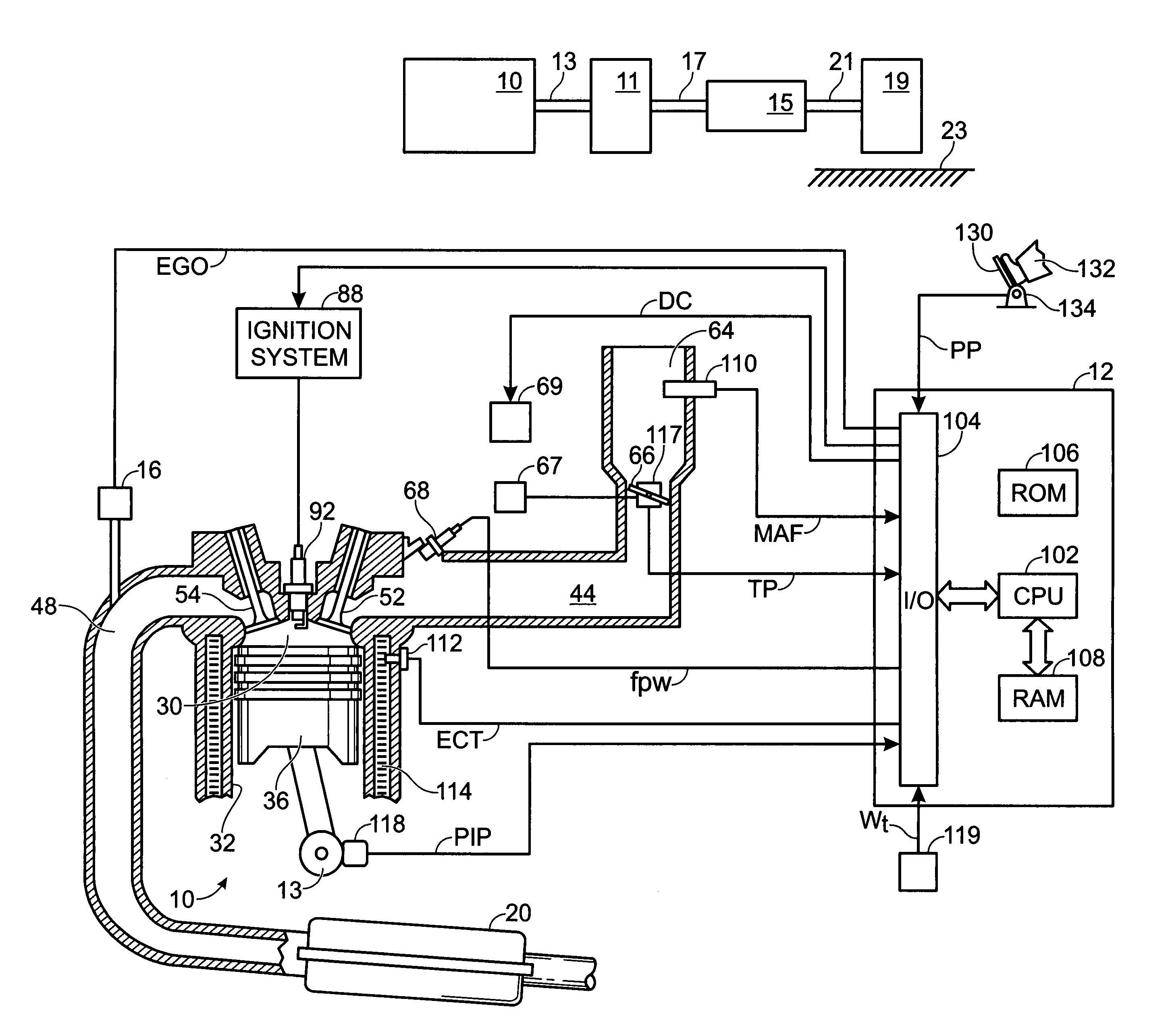
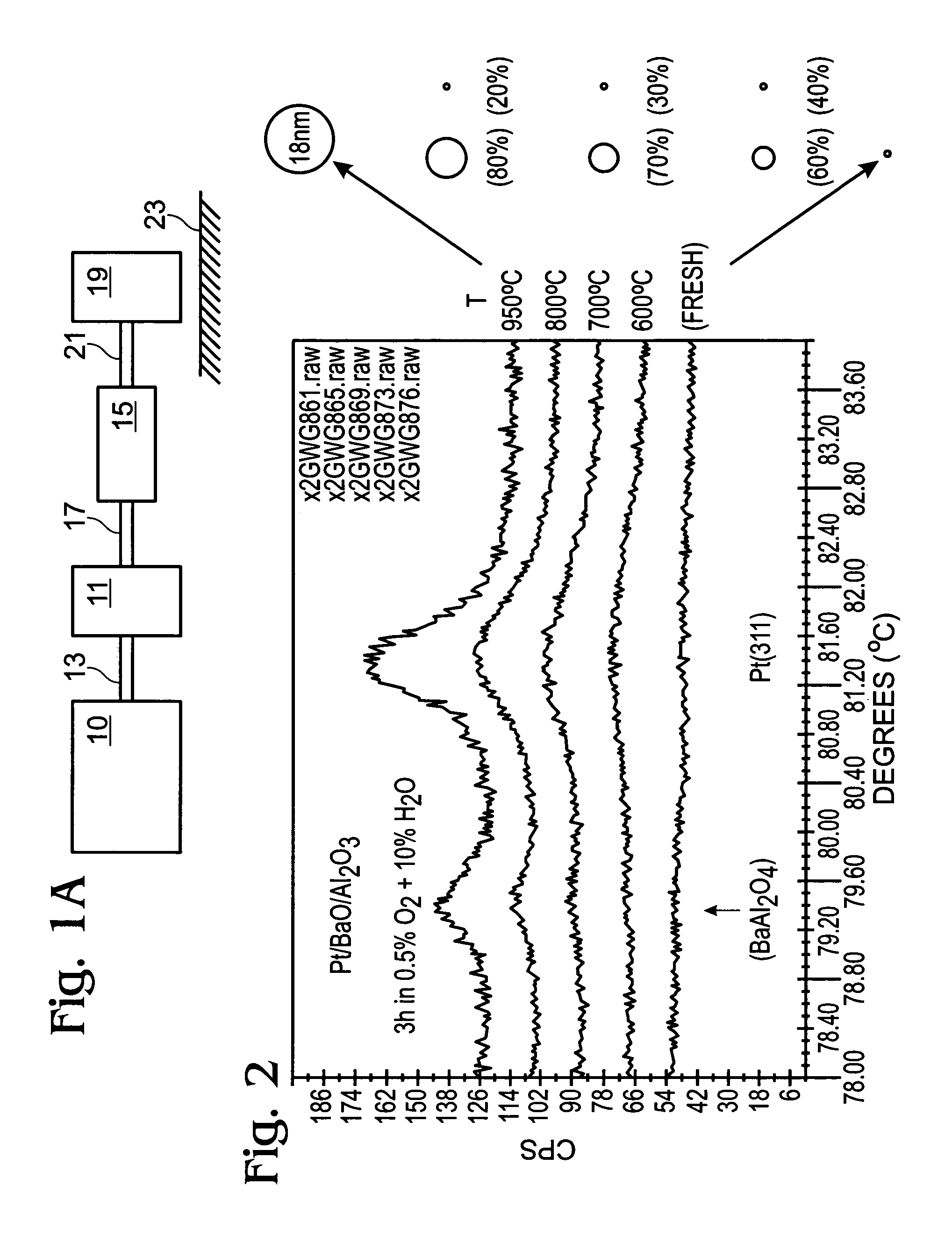
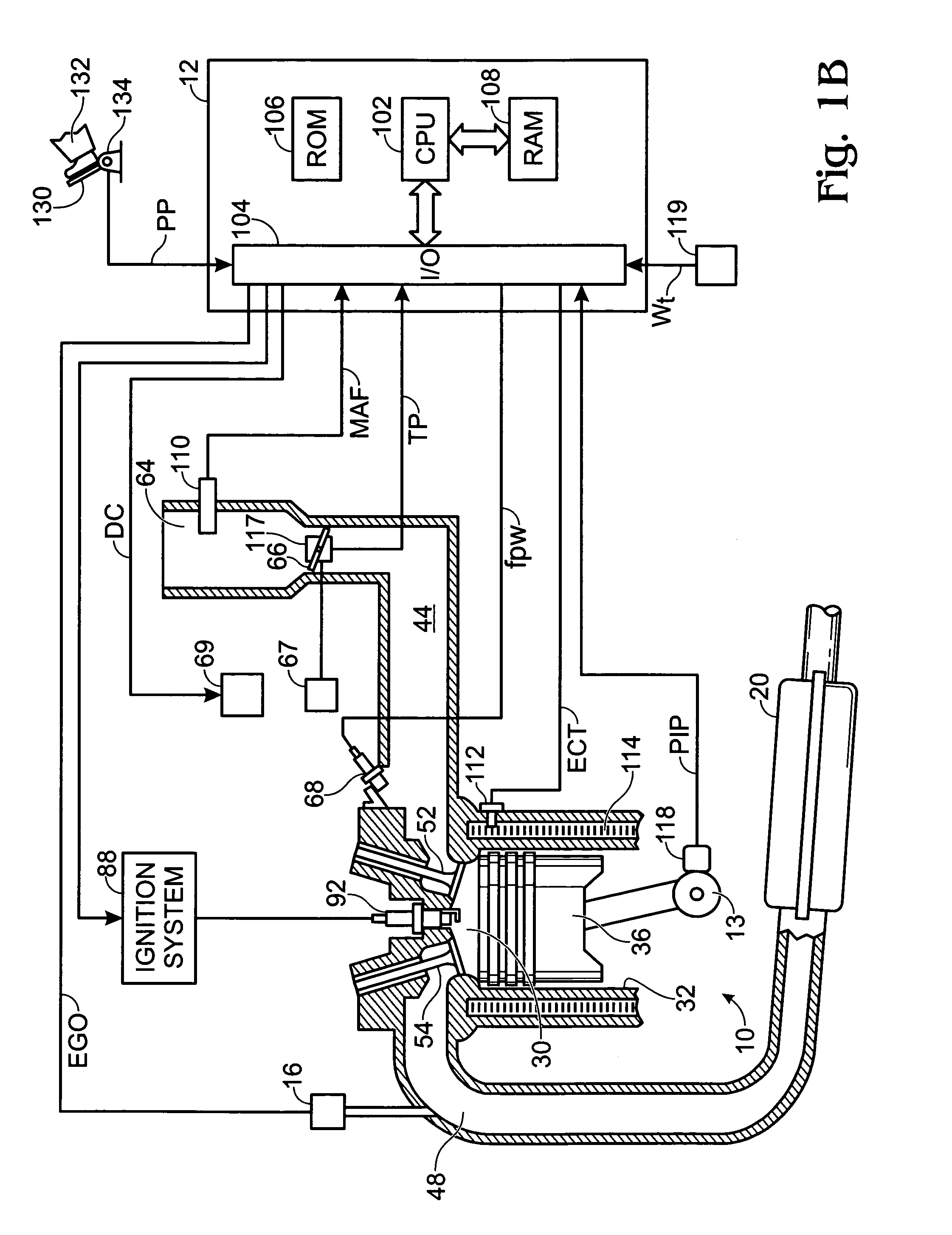
[0023]Referring to FIG. 1A, internal combustion engine 10, further described herein with particular reference to FIG. 1B, is shown coupled to torque converter 11 via crankshaft 13. Torque converter 11 is also coupled to transmission 15 via turbine shaft 17. Torque converter 11 has a bypass clutch (not shown) which can be engaged, disengaged, or partially engaged. When the clutch is either disengaged or partially engaged, the torque converter is said to be in an unlocked state. Turbine shaft 17 is also known as transmission input shaft. Transmission 15 comprises an electronically controlled transmission with a plurality of selectable discrete gear ratios. Transmission 15 also comprise various other gears, such as, for example, a final drive ratio (not shown). Transmission 15 is also coupled to tire 19 via axle 21. Tire 19 interfaces the vehicle (not shown) to the road 23.

[0024]Internal combustion engine 10 comprising a plurality of cylinders, one cylinder of which is shown in FIG. 1B...


PUM


Abstract

A system is described for improving engine and vehicle performance by considering the effects of exhaust conditions on catalyst particle growth. Specifically, engine operation is adjusted to reduce operating in such conditions, and a diagnostic routine is described for determining the effects of any operation that can cause such particle growth. Further, routines are described for controlling various vehicle conditions, such as deceleration fuel shut-off, to reduce effects of the particle growth on emission performance.

Description

FIELD OF THE INVENTION[0001]The field of the present invention relates to controlling engine air-fuel ratio operating during high temperature lean operation to prevent growth of precious metal particle size in an emission control device.BACKGROUND AND SUMMARY OF THE INVENTION[0002]Lean-burn gasoline engines can be more efficient and thus use less fuel and produce less carbon dioxide than corresponding engines operating under stoichiometric conditions.[0003]To approach to treat engine emissions is to catalytically convert NO to a solid, prototypically barium nitrate, and store it in an emission control device during lean operation. The device is regenerated periodically by briefly shifting engine operation to stoichiometric or rich conditions, under which the barium nitrate becomes released NO that is then reduced. The operating temperature range for the device can be determined by the activity of the catalyst used to form the solid nitrate (defining the lower limit) and the stabilit...

Claims


Application Information

Patent Timeline
Patent Type & Authority Patents(United States)
IPC IPC(8): F01N11/00G06G7/70
CPCF01N11/002F01N2570/04Y02T10/47Y02T10/40
Inventor SURNILLA, GOPICHANDRAGANDHI, HARENDRA S.GORALSKI, JR., CHRISTIAN T.MCCABE, ROBERT W.GRAHAM, GEORGEJEN, HUNGWEN
Owner FORD GLOBAL TECH LLC
Why Eureka
Try Eureka