Electrical connector and socket assemblies

a technology of electrical connectors and sockets, applied in the direction of contact members penetrating/cutting insulation/cable strands, coupling device connections, etc., can solve the problems of limited insulating material length that can be provided around the parts, affecting the sealing integrity of the seal, and affecting the electrical integrity of the electrical connector. , to achieve the effect of increasing electrical integrity

Inactive Publication Date: 2007-09-04
OILFIELD EQUIP DEVMENT CENT
View PDF70 Cites 102 Cited by
  • Summary
  • Abstract
  • Description
  • Claims
  • Application Information

AI Technical Summary

Benefits of technology

[0016]The provision of a separate spigot for each of the conductors and for sealing engagement within a respective recess in a body of the assembly enables the spigots to be sealingly fitted to the conductors prior to each spigot being introduced into its recess and sealingly engaged therein. When provided in a motor the separate spigot allows the conductor terminal to be parallel with the motor shaft and therefore permits an elongated connector assembly internal to the motor. This provides improved insulation of the conductor and increased creepage distance between the mating electrical parts and the outer surface of the housing of the assembly. It also provides the additional advantage that the seal on the conductor tends to be smaller than in prior arrangements so that there is less thermal expansion of the seal when the parts get hot in a downhole environment.
[0018]Such an arrangement permits a relatively long creepage path between the mating electrical parts and the outer surface of the housing of the assembly.
[0020]Such an arrangement has the advantage that the primary sealing means with respect to the conductor no longer bears against the conductor insulation that is liable to swell when subjected to the high temperature downhole environment. Instead the sealing means bears against the outer surface of the conductive terminating pin which is much more stable at high temperatures. An insulating barrier preferably covers the pin / conductor connection to provide increased electrical integrity. Most preferably the barrier is sealed with elastomeric calk, with a crimped lead sheath or by crimping of the barrier itself to a lead sheath so as to render the connection gas tight.

Problems solved by technology

However, the angled pothole limits the length of the mating electrical parts of the connector and socket assemblies, and consequently limits the length of insulating material that can be provided around the parts to provide a long creepage distance between the outside of the connector assembly and the electrical interface between the connector and socket assemblies.
Furthermore, because the primary seal with respect to each conductor from the cable bears against the conductor insulation and the conductor insulation is liable to swell when subjected to the high temperature environment of the well, the seal integrity is compromised.
Such an arrangement suffers from the fact that the primary seal with respect to each conductor bears against the conductor insulation and the conductor insulation is liable to swell when subjected to the high temperature environment of the well.
Furthermore, as the elastomeric materials of the insulation and the seal increase in volume, the insulation can be damaged or the seal integrity diminished.
Motors with thrust bearings in the top cannot have the connector on top of the motor as it is not possible for the three insulated conductors from the cable to be passed beyond the bearing.
However the three insulated conductors from the cable extend through three parallel passages in a common sealing gland, and thus there are again difficulties in terms of the integrity of the seals in a downhole environment.
However each of the conductors is sealed within the corresponding pothole by a respective O-ring seal, so that there are difficulties in assembly as well as in the integrity of the sealing as a result of the direct sealing of the O-ring seal on the conductor insulation.
Also there is insufficient strain relief for the conductors with the result that there is a risk that the conductors will be pulled out of the motor when it is installed in a well.
However the three insulated conductors from the cable extend through three passages in a common insulating block, and thus there are again difficulties in terms of the integrity of the sealing in a downhole environment.
This means that there is little control over the relative rotational positions of the pothole and the motor stator within the housing.
Such winding of the leads around the motor shaft during assembly can introduce further possible failure mechanisms, and it is not possible to observe the twisted motor leads and their connection to the stator windings once the motor head has been assembled with the motor housing.
Any resulting chafing, cuts or strain on the internal electrical joints may not be revealed during initial electrical testing but may remain as a weak point during long-term service.

Method used


Image

  • Electrical connector and socket assemblies
  • Electrical connector and socket assemblies
  • Electrical connector and socket assemblies

Examples


Embodiment Construction

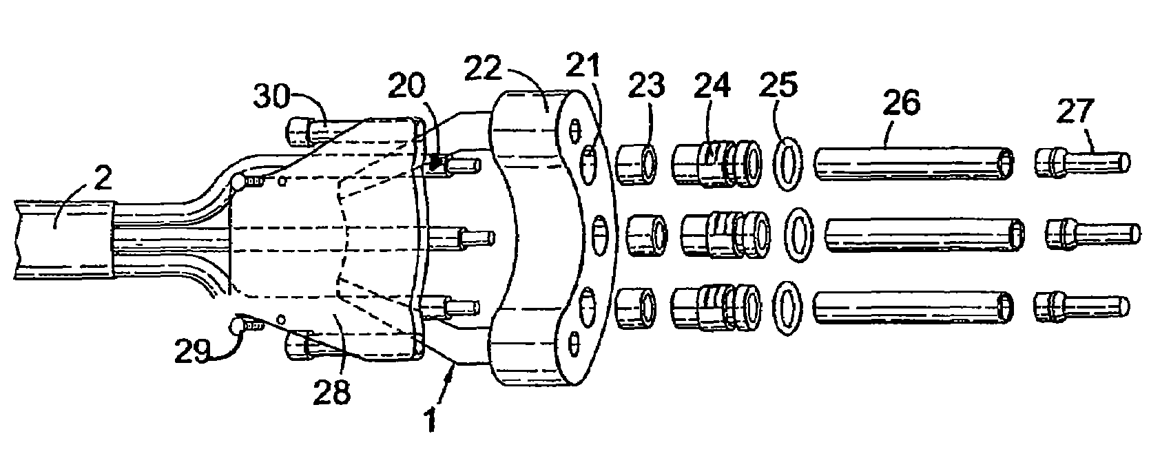
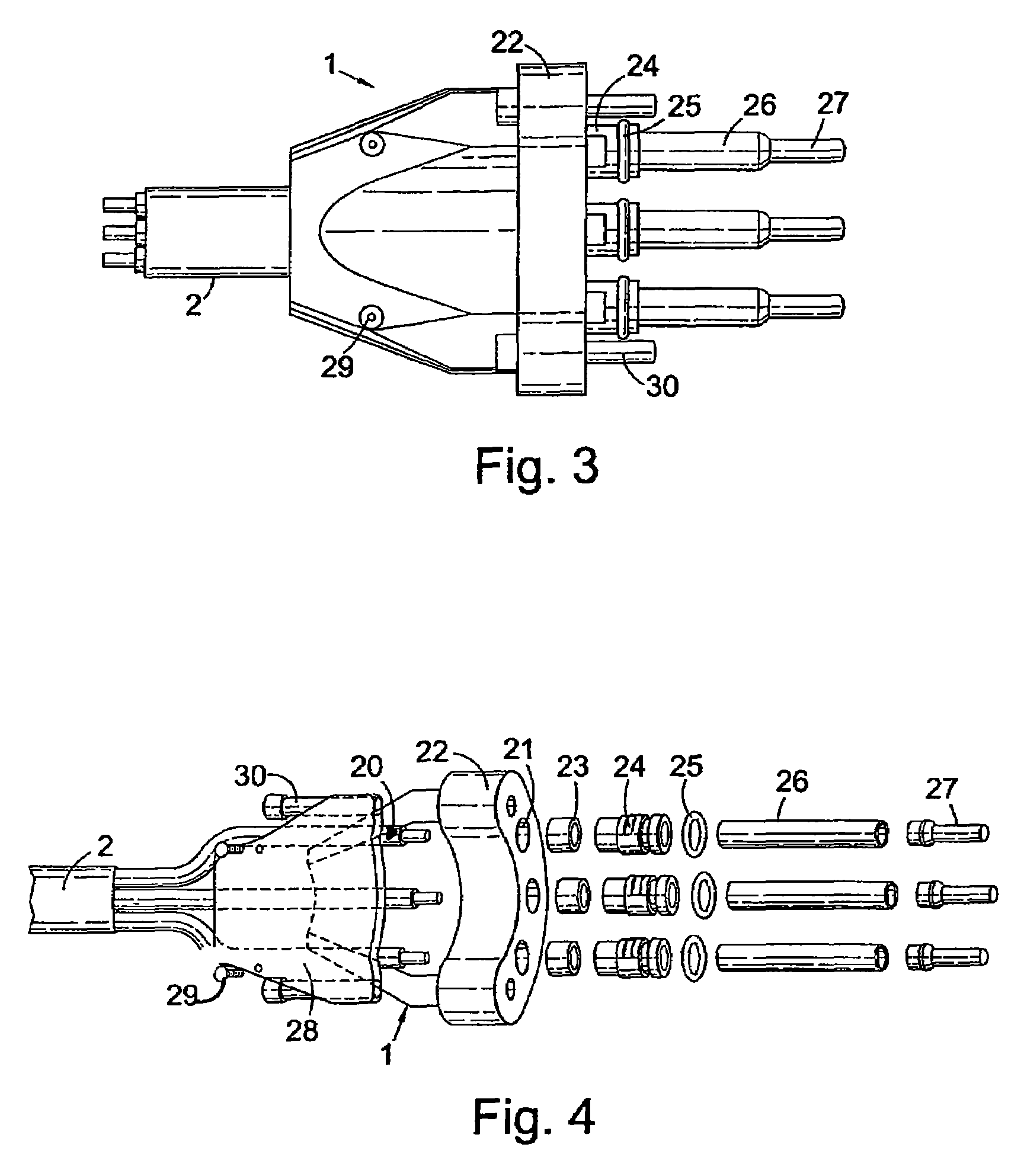
[0031]The embodiments of the invention described below with reference to the drawings relate to the connection of power cables to the motors of ESP's, although it will be appreciated that other connector and socket assemblies in accordance with the invention can be used for other purposes, and this particular application is only given by way of example.

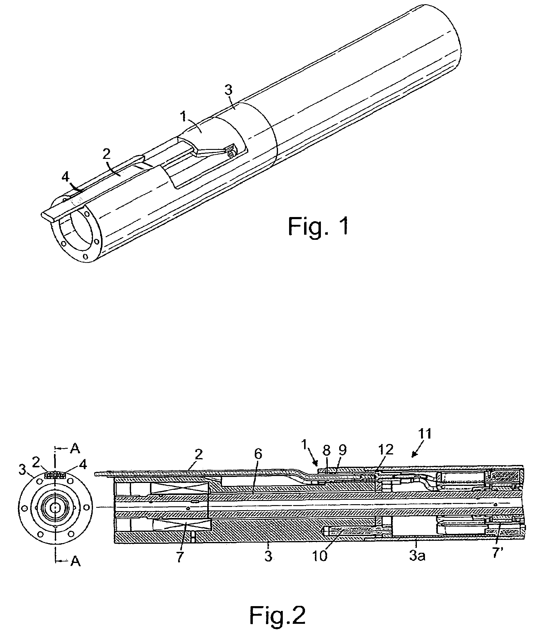
[0032]Referring to FIG. 1, this shows the electrical connector assembly 1, that is the pothead, and the end of a cable 2 for supplying power from the surface plugged into the motor head 3 so as to establish an electrical connection with the windings of the motor stator. As shown the cable 2 extends within a slot 4 in the motor head 3.

[0033]The cable used is typical for ESP applications and contains multiple conductors that have one or more layers of insulation with one or more layers of protective material. Three conductor flat cable with an interlocking metal armour with each conductor protected by a lead sheath, EPDM (ethylene propy...


PUM


Abstract

An electrical connector assembly for a cable having a plurality of insulated conductors comprises a body having a respective recess for receiving a terminating pin each of the conductors. A respective spigot sealingly engages within each of the recesses and has a passage for receiving an associated one of the terminating pins. Furthermore a seal is associated with each of the spigots for sealing the spigot relative to the associated terminating pin. The provision of a separate spigot for each of the conductors and for sealing engagement within a respective recess in the body enables the spigots to be sealingly fitted to the conductors prior to each spigot being introduced into its recess and sealingly engaged therein. This provides improved insulation of the conductor and increased creepage distance between the mating electrical parts and the outer surface of the housing of the assembly. It also provides the additional advantage that the seal on the conductor tends to be smaller than in prior arrangements so that there is less thermal expansion of the seal when the parts get hot in a downhole environment.

Description

CROSS-REFERENCE TO RELATED APPLICATIONS[0001]The present application is based on, and claims priority from, British Application Serial Number 0426585.6, filed Dec. 6, 2004, the disclosure of which is hereby incorporated by reference herein in its entirety.BACKGROUND OF THE INVENTION[0002]1. Filed of the Invention[0003]This invention relates to electrical connector assemblies for cables having a plurality of insulated conductors, and to socket connector assemblies for electrical connection to such connector assemblies, and is more particularly, but not exclusively, concerned with such connector and socket assemblies for use with electric submersible pumps and compressors.[0004]2. Description of the Related Art[0005]Electric submersible pumps (ESP) are installed in subterranean wells for extracting hydrocarbons where the natural pressure in the reservoir is insufficient to lift the fluid or gas to the surface. The ESP motor is powered through a cable that connects the motor to a power...

Claims


Application Information

Patent Timeline
Patent Type & Authority Patents(United States)
IPC IPC(8): H01R13/52H01RH01R13/405H01R13/523
CPCH01R13/405H01R13/521H01R13/523E21B43/01H01R13/424H01R13/44H01R13/52H01R13/5208H01R13/5219H01R13/56
Inventor KENNEDY, STEVEN CHARLESYURATICH, MICHAEL ANDREWKOPECKY, TREVOR ALANFRASER, ALAN THOMAS
Owner OILFIELD EQUIP DEVMENT CENT
Why Eureka
Try Eureka