Protein skimmer

a technology of protein skimmer and skimmer head, which is applied in water cleaning, water/sewage multi-stage treatment, separation process, etc., can solve the problems of unsatisfactory, less fish growth, and more bubbles in the water in fresh water, so as to reduce fish growth and increase the water content

Active Publication Date: 2007-09-04
CLARITY
View PDF13 Cites 8 Cited by
  • Summary
  • Abstract
  • Description
  • Claims
  • Application Information

AI Technical Summary

Benefits of technology

[0008]U.S. Pat. No. 4,988,436 (Cole) comprises a protein skimmer (shown in FIGS. 1 and 2 of the US Patent) with an air injection pump 71 and an air tube 129 to bubble diffusers 127 and 131, which form bubbles which gather in the extraction chamber 99 in which protein foam is collected. The disadvantage of the invention described in this US Patent is again the undesirable air injection.
[0009]U.S. Pat. No. 5,628,905 (Montalbano) describes a further protein skimmer with air injection to a porous bubble diffuser, please see reference numerals 41 in FIG. 3 and 4 in the US Patent.
[0010]U.S. Pat. No. 5,736,034 (Phillips) shows a tangential horizontal inlet for a mixture of water and air from a pump to a vertical tube having a larger diameter than the horizontal inlet, in which a vortex is formed, and in which the vortex is guided up through a central tube to the surface at which it is formed foam that may be skimmed. The present invention essentially differs from this.
[0011]U.S. Pat. No. 6,156,209 (Kim) shows a bubble chamber with air at the top. In the bubble chamber water is flushed down towards the surface of the water, in which foam is formed, gathers on the surface and rises up in a foam riser. Water having a less protein content is collected near the bottom of the bubble chamber. This US Patent does not show a rearward directed side branch of a water tube.
[0012]U.S. Pat. No. 6,303,028 (Marks et al.) shows protein foam formation at the water-air contact when an air / water mixture is circulated across a barrier within an inverted funnel. Protein foam is formed and oozes up and out through the upper, narrower opening of the funnel and may be drained from an upper tank. This does not show any straight portion on the discharge tube. Further, the US Patent requires admixture of air and does not show any rearward inclined side branch, as opposed to the present invention.
[0013]The above mentioned background art does not solve the problem which arises at a too large nitrogen content level in the fresh water, and which leads to reduced fish growth. The above publications further relate to methods for use in saline water. In saline water smaller-bubbles will form than would be the case in fresh water. The bubble formation in fresh water creates bubbles of such size, see FIG. 12, that the fry may confuse bubbles and feed, which incurs that the fry may end up higher in the water than is favourable for the fry's light conditions, temperature, or the risk of being eaten, or that it receives insufficient amount of feed. In other words, there is a need for a protein skimmer that avoids the disadvantages with the above publications.

Problems solved by technology

Injection of bubbles is a disadvantage because of the danger of increased nitrogen content in the water, which usually leads to poorer fish growth.
Bubbles in the water are more easily formed in fresh water and is not desirable because the fry may confuse air bubbles with feed particles.
The supply of pressurized air is undesirable as explained above.
The disadvantage of the invention described in this US Patent is again the undesirable air injection.
The above mentioned background art does not solve the problem which arises at a too large nitrogen content level in the fresh water, and which leads to reduced fish growth.
The bubble formation in fresh water creates bubbles of such size, see FIG. 12, that the fry may confuse bubbles and feed, which incurs that the fry may end up higher in the water than is favourable for the fry's light conditions, temperature, or the risk of being eaten, or that it receives insufficient amount of feed.

Method used


Image

  • Protein skimmer
  • Protein skimmer
  • Protein skimmer

Examples


Embodiment Construction

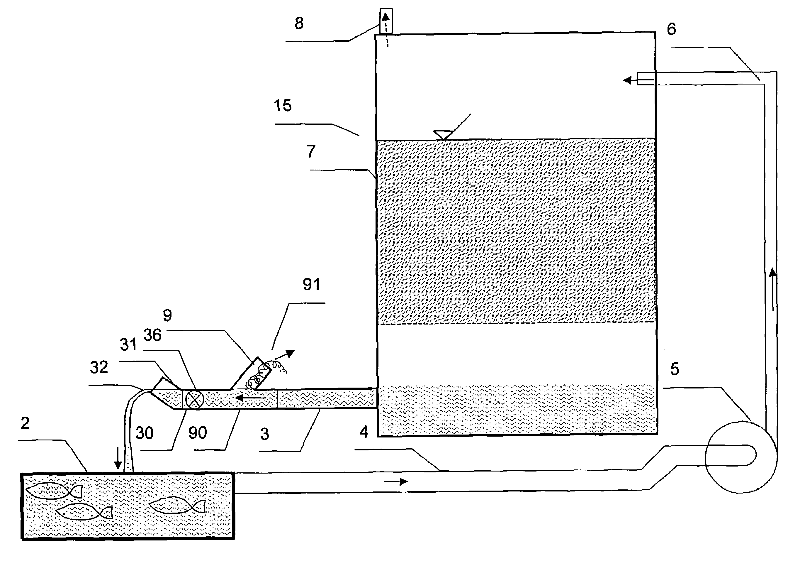
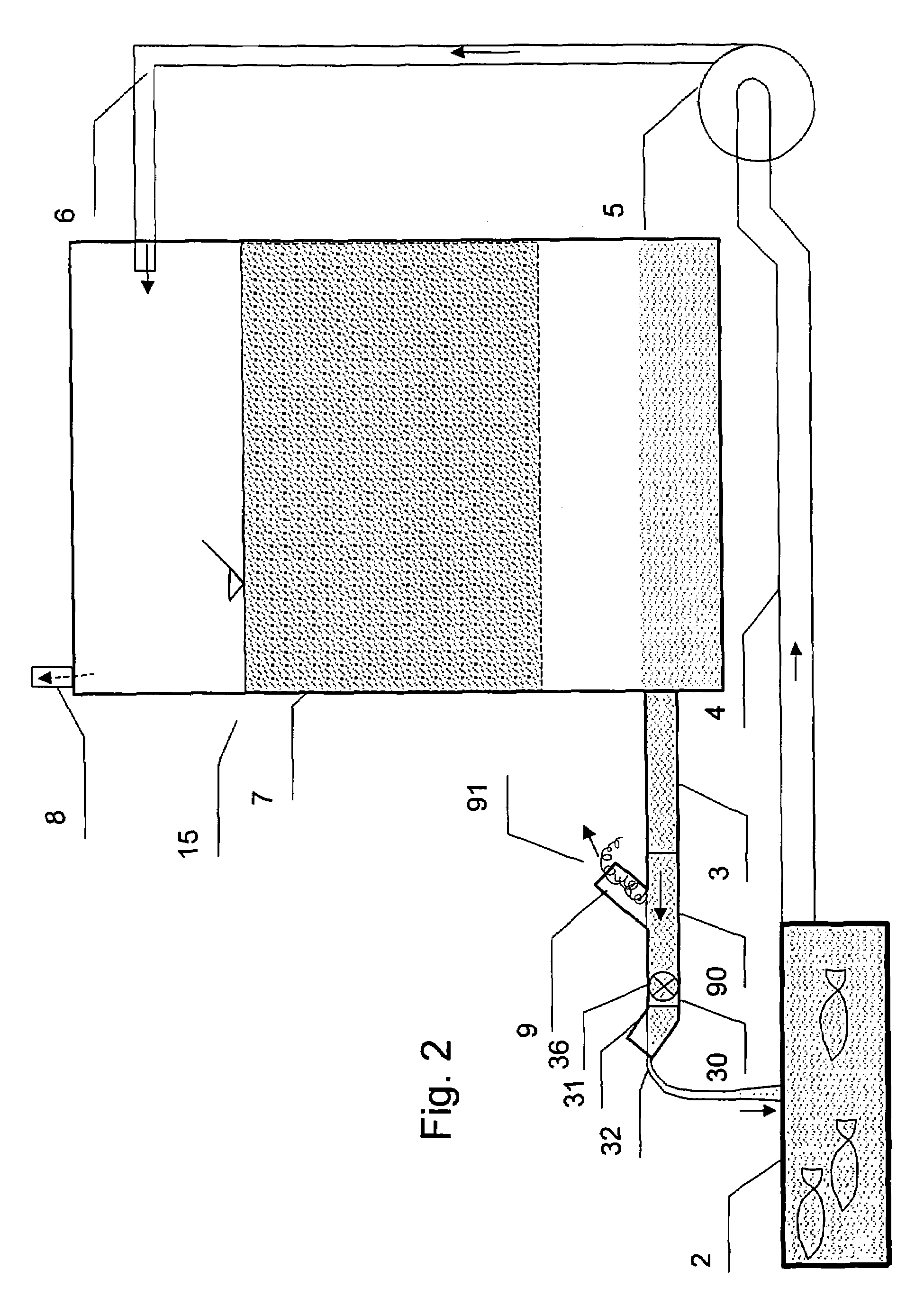
[0037]Reference is now made to FIG. 1, in which a simple aquaculture or mariculture installation with a reservoir 2 for culture of fresh water fish or salt water fish or other water-living organisms, with a protein skimmer according to a possible embodiment of the invention. A discharge tube 4 for water is arranged from the reservoir 2 to a pump 5 for circulation of the water, together with a return tube 3 for water from the pump 5 to the reservoir 2. Further in this embodiment it is shown a filter tank 1 with a particle filter 7 that is arranged between the discharge tube 4 from the reservoir 2 and the return tube 3 to the reservoir 2. A side branch 9 is arranged on a generally horizontal, straight portion 90 in the return tube 3. The end or outlet 31 of the return tube 3 is here shown arranged in an upward, oblique angle with respect to the horizontal main channel of the return tube 3.

[0038]The protein skimmer according to the invention is arranged for use by purification of fresh...


PUM

PropertyMeasurementUnit
angleaaaaaaaaaa
angleaaaaaaaaaa
angleaaaaaaaaaa

Abstract

A protein skimmer for use in purification of water by culture of fish or other water organisms in a reservoir, aquarium or (2) with a circulation system comprising one or more discharge tubes (4) for water from the reservoir (2) to a pump (5) for circulation of the water, and a return tube (3) for water directly or indirectly from the pump (5) to the reservoir (2) The return tube (3) comprises at least one generally horizontal, straight portion (90) having one or more upwardly directed side branches (9) which has an opening (91) leading to air, in which the generally horizontal straight portion (90) is arranged for rapid passage of the water past. the side branch (9) and to have the water level at or above the intersection of the side branch (9) with the straight portion (90), and in which the side branch (9) is directed rearward relative to the direction of the water flow in the straight portion (90), and forms a first angle (v) with between 0° and about 90° with the straight portion (90).

Description

[0001]The present invention relates to a separator, also called a deskimmer or skimmer, for removal of protein from water in aquaculture installations and aquariums. In particular, the invention relates to a protein skimmer for water circulation in an aquaculture installation for edible fish or aquarium for relatively large amounts of aquarium fish, e.g., Koi fish, or other-fresh water fish species, or for other fresh water organisms, e.g. cray fish. The protein skimmer according to the invention may also be used for removing protein from sea water in culture tanks for marine organisms.BACKGROUND OF THE INVENTION [0002]One problem that the inventor has tried to overcome by means of the present invention is to reduce the supply of air to the water during the purifying process for removing protein from the water. If air is supplied to the water in the form of pressurized air or bubbles, much of the nitrogen gas in the air will be dissolved in the water. This may lead to undesired nitr...

Claims


Application Information

Patent Timeline
Patent Type & Authority Patents(United States)
IPC IPC(8): C02F1/40A01K63/04
CPCA01K63/045C02F1/40C02F2101/38C02F2103/20C02F2303/12Y10S210/905
Inventor JONEID, STEINAR
Owner CLARITY
Why Eureka
Try Eureka