
Ultra-broadband integrated balun

a balun and ultra-broadband technology, applied in the field of communication systems, can solve the problems of limiting the operational bandwidth of the spiral transformer, and the bandwidth limitations of the ring hybrid coupler

Active Publication Date: 2007-09-04
IBM CORP
View PDF5 Cites 15 Cited by
  • Summary
  • Abstract
  • Description
  • Claims
  • Application Information

AI Technical Summary

Benefits of technology

The present invention provides an ultra-broadband balun that overcomes problems in previous designs. The balun includes a first unbalanced transmission line and a balanced transmission line connected together through a first capacitor. The balun can be used in millimeter wave and microwave transmissions. The first unbalanced transmission line has a first ground trace and a signal trace connected together through the first capacitor. The balun circuit has improved impedance and power output. The first unbalanced transmission line can also include a second ground trace and a second capacitor in series with the signal trace. The balun circuit includes a bias-tee formed by the first and second bias stubs. The technical effects of the invention include improved impedance and power output, as well as improved impedance and power output in millimeter wave and microwave transmissions.

Problems solved by technology

The spiral transformer, however, is inherently narrow band due to its non-idealities.
This leads to parasitics that have to be resonated out, thus limiting the operational bandwidth of the spiral transformer.
The ring hybrid coupler has bandwidth limitations because the size of the ring structure is determined by the wavelength λ of the desired signal.
The inclusion of these capacitors would, however, lead to discontinuities such as an impedance mismatch or insertion loss within the signal traces 250a,b.

Method used


Image

  • Ultra-broadband integrated balun
  • Ultra-broadband integrated balun
  • Ultra-broadband integrated balun

Examples


Embodiment Construction

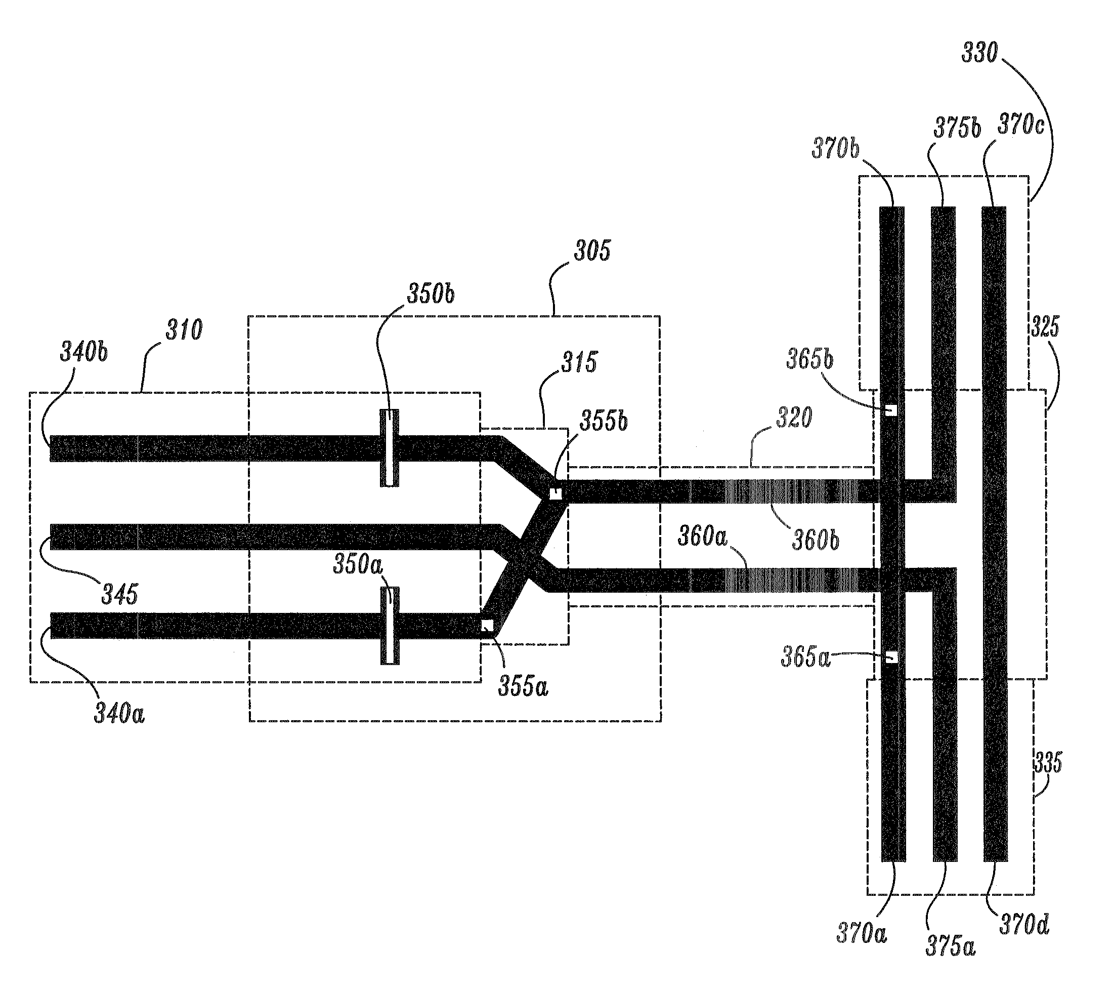
[0035]FIG. 3 is a diagram of an ultra-broadband balun structure according to an exemplary embodiment of the present invention. As shown in FIG. 3, an ultra-broadband balun 305 includes a portion of an unbalanced transmission line 310, a portion of a balanced transmission line 320 and a transition 315 between the unbalanced transmission line 310 and the balanced transmission line 320. The balun 305 also includes a pair of capacitors 350a,b connected to the unbalanced transmission line 310.

[0036]The unbalanced transmission line 310 includes a pair of ground traces 340a,b and a signal trace 345. The capacitors 350a,b are inserted in a portion of the ground traces 340a,b that are included in the balun 305. The balanced transmission line 320 includes a pair of signal traces 360a,b. One of the signal traces 360a is connected to the signal trace 345 and the other signal trace 360b is connected to the ground traces 340a,b through the transition 315 followed by the capacitors 350a,b. The tra...


PUM


Abstract

An ultra-broadband balun is provided. The balun comprises: a first unbalanced transmission line comprising a first ground trace and a signal trace; and a balanced transmission line comprising a first and second signal trace, wherein the first signal trace of the balanced transmission line is connected to the first ground trace of the first unbalanced transmission line and the second signal trace of the balanced transmission line is connected to the signal trace of the first unbalanced transmission line, wherein a first capacitor is disposed in series with one of the first ground trace of the first unbalanced transmission line and the first signal trace of the balanced transmission line.

Description

BACKGROUND OF THE INVENTION[0001]1. Technical Field[0002]The present invention relates to communications systems, and more particularly, to millimeter-wave transmission lines and hybrid couplers.[0003]2. Discussion of the Related Art[0004]A conventional balun is used to convert balanced or differential signals into unbalanced or single-ended signals. Baluns have found increasing use in circuits for millimeter-wave, radio frequency (RF), and high-speed wired applications. The integration of baluns with circuit elements has led to a reduction in power consumption, input / output ports, size and cost of balun-equipped circuits. Moreover, baluns for such circuit integration should be broadband and compact and have a low insertion loss and good return loss.[0005]At low frequencies, for example, 1-5 GHz, integrated baluns are typically implemented using a spiral transformer. Spiral transformers work by exploiting magnetic coupling between inner wound coils of its spiral. The spiral transfor...

Claims


Application Information

Patent Timeline
Patent Type & Authority Patents(United States)
IPC IPC(8): H01P5/10H03H7/42
CPCH01P5/10
Inventor FLOYD, BRIAN A.ZWICK, THOMAS M.
Owner IBM CORP
Learn More