Mirror holding method and optical apparatus

Inactive Publication Date: 2007-09-04
CANON KK
View PDF5 Cites 0 Cited by
  • Summary
  • Abstract
  • Description
  • Claims
  • Application Information

AI Technical Summary

Benefits of technology

[0008]A mirror holding method according to the present invention, for example, wherein a symmetry axis of an illuminating area substantially corresponds with that of a mirror holder in an optical system, and a center of the illuminating area in a mirror differs from a centroid of the mirror. For example, even if the center in the illuminating area of the mirror differs from the centroid in the mirror, stress distribution that occurs from heat generated by exposure light in the mirror is symmetrical on both sides of a symmetry axis because a symmetry axis in an illuminating area (substantially) corresponds with that of the mirror holder. Thus, it is possible to change deformation of the mirror's surface into symmetric.
[0010]A mirror holding method, wherein a center of the illuminating area may (substantially) corresponds with that of the mirror holder. According to the mirror holding method, it is able to prevent large displacement, which results from thermal expansion in a center position of an illuminating area on the mirror because light is illuminated to a center of the mirror holder.
[0012]A mirror holding method, wherein a centroid of the illuminating area may (substantially) correspond with that of the mirror holder. According to the mirror holding method, it is able to prevent large displacement, which results from thermal expansion in a centroid position of an illuminating area on the mirror because light is illuminated to a center of the mirror holder.
[0014]Another mirror holding method according to the present invention, wherein the mirror may reflect Extreme Ultraviolet Radiation (EUV) light. When EUV light is illuminated to the mirror, even if the mirror has a large rate of EUV light absorption, the mirror holding method may change the surface deformation in the mirror into symmetric, and reduce deformation which deteriorates optical performance.

Problems solved by technology

The increasing temperature causes bad aberration due to thermal expansion and extreme deformation of the mirror.
However, although it is able to inhibit rising temperature, it is not able to absolutely prohibit the rising temperature in the whole mirror from deforming the mirror.
However, the mirror cannot have simple expansion or contraction because the symmetry axis of an illuminating area on the mirror, in this kind of conventional mirror holder, differs extremely from that of the mirror holder.

Method used


Image

  • Mirror holding method and optical apparatus
  • Mirror holding method and optical apparatus
  • Mirror holding method and optical apparatus

Examples


first embodiment

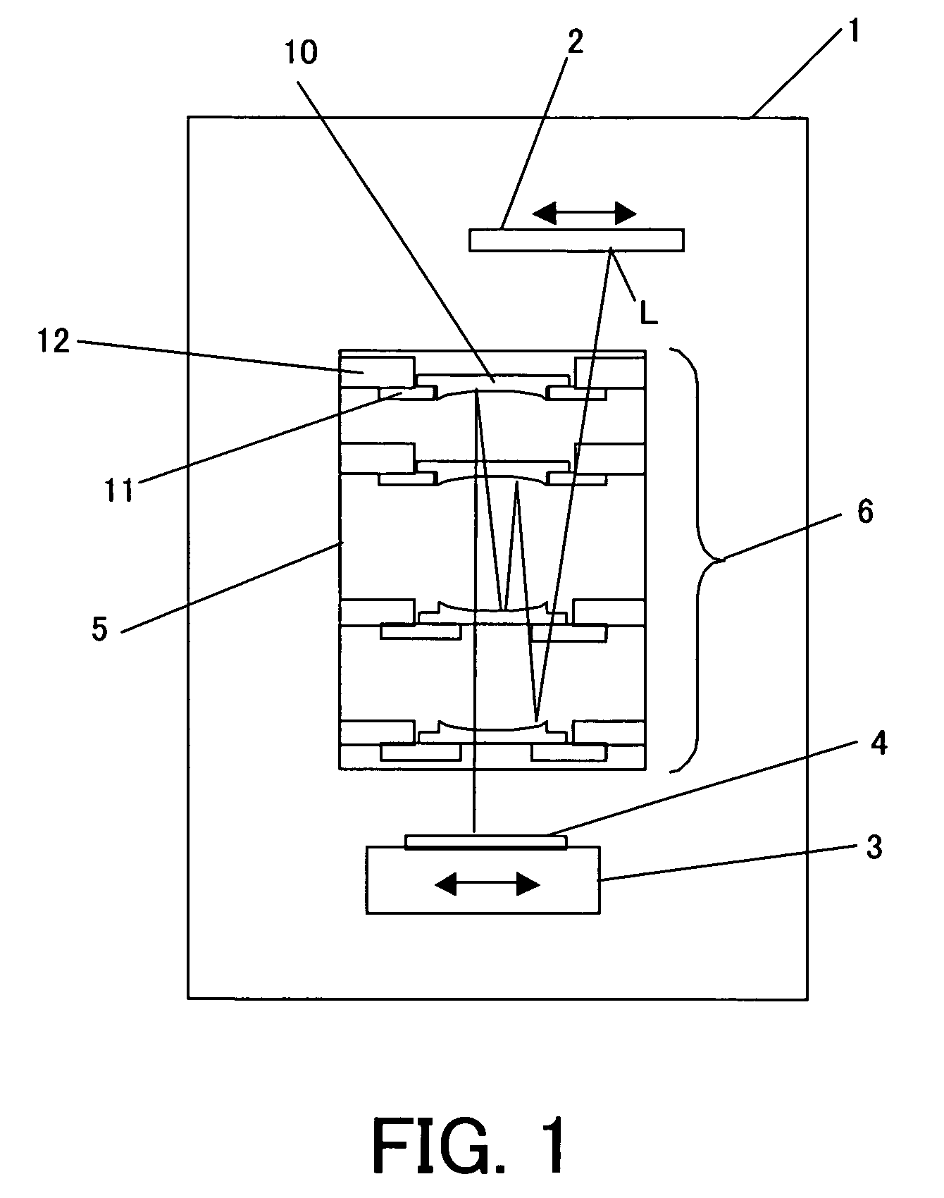
[0025]FIG. 1 is a schematic structure view of an exposure apparatus with a mirror holding method of a first embodiment according to the present invention. The exposure apparatus, by using EUV light with a wavelength of about 13 nm to illuminate a mask, uniformly illuminates a reflecting type mask and projects a pattern of the mask onto a wafer.

[0026]In FIG. 1, 1 is a chamber that divides an exposure atmosphere in air, and is vacuum-pumped by a pump (not shown). An exposure light L, reflected by a reticle 2, passes a projecting optical system 6 and is illuminated onto a wafer 4. A pattern on the reticle 2 is transferred onto a wafer 4 that is arranged on a wafer stage 3.

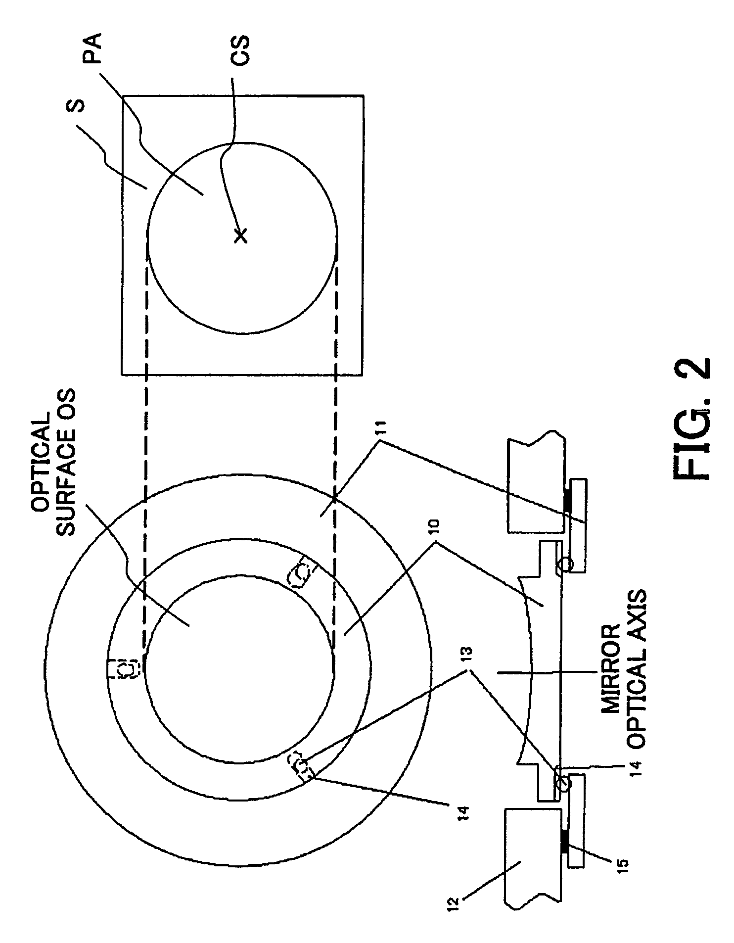
[0027]FIG. 2 is a view of a mirror and a mirror holder according to the present invention. A mirror holding member 12, which holds a mirror-supporting member 11, is fixed on a wall of a bodytube 5. A position controller 15, arranged between the mirror-supporting member 11 and the mirror holding member 12, controls the...

second embodiment

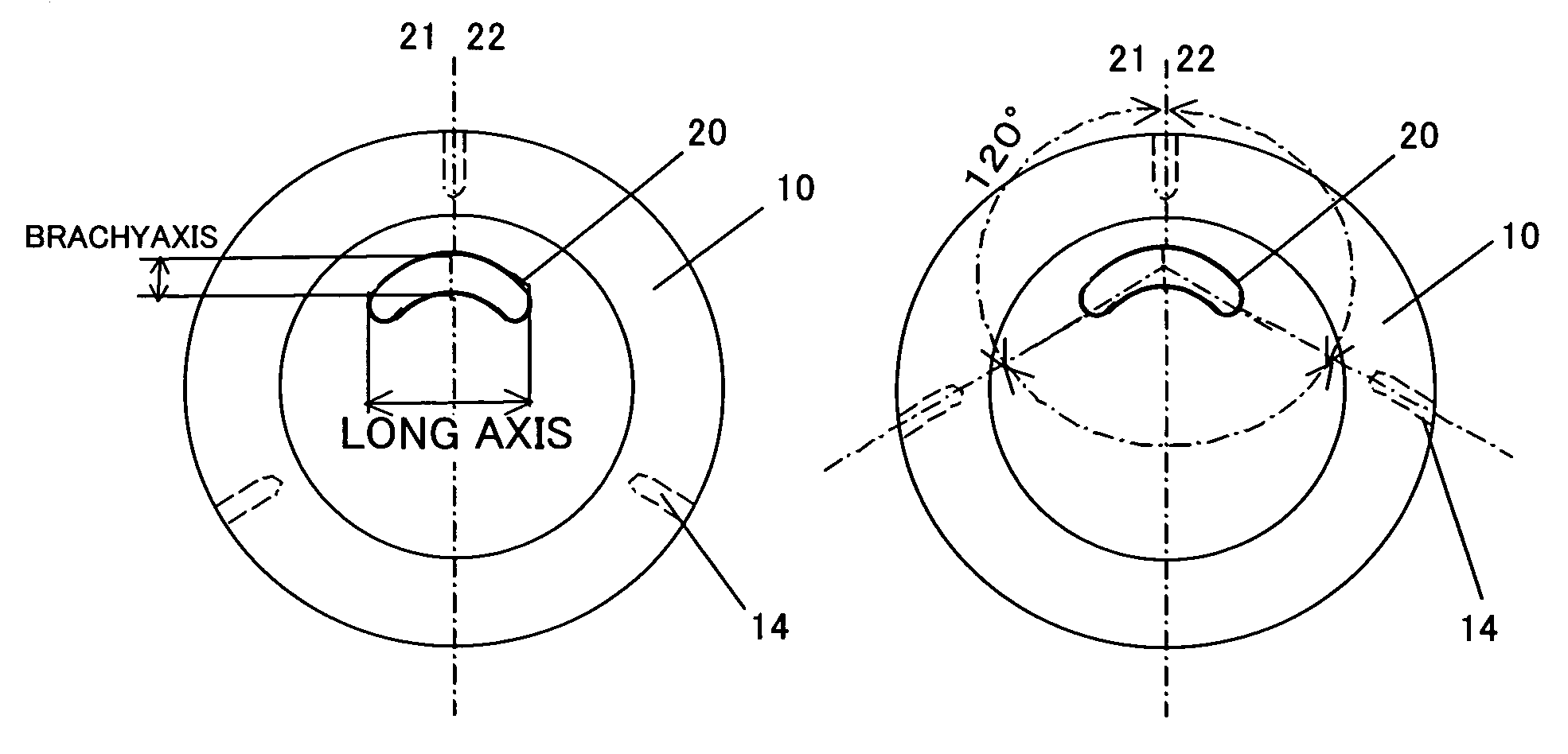
[0032]FIG. 4 shows the second embodiment according to the present invention. An illuminating area of exposure light in FIG. 4 is an ellipse. As shown in FIG. 4A, a holder is arranged so that the symmetry axis 22, in the illuminating-area 20, of the exposure light, corresponds with the symmetry axis 21 in the mirror holder. Thus, the mirror 10 may distort symmetrically, and surface deformation, which deteriorates optical performance, is lowered. In the instant embodiment, the symmetry axis 22, of the exposure light's illuminating area 20, corresponds absolutely with the symmetry axis 21 of a mirror's 10 holding point. Furthermore, the present invention may achieve the above effect even when an error angle between the symmetry axis 22, of the exposure light's illuminating area 20 and the symmetry axis 21 of a mirror's 10 holding point is within 10° or less.

[0033]FIG. 4B shows the correspondence of the symmetry axis 22 in the exposure light's illuminating area with the symmetry axis 21...

third embodiment

[0034]FIG. 5 shows a third embodiment according to the present invention. An exposure light's illuminating area, as shown in FIG. 5, is intermediate shape between a radii and an ellipse. A holding point is arranged so that the symmetry axis 22 of the exposure light's illuminating area 20 corresponds with the symmetry axis 21 in the mirror holder. Thus, the mirror 10 may distort symmetrically, and surface deformation, which deteriorates optical performance, is lowered. In the instant embodiment, the symmetry axis 22 in the exposure light's illuminating area 20 corresponds absolutely with the symmetry axis 21 of a mirror's 10 holding point. Furthermore, the present invention may achieve the above effect even when an error angle between the symmetry axis 22 in the exposure light's illuminating area 20 and the symmetry axis 21 of a mirror's 10 holding point is within 10° or less.

[0035]FIG. 5B shows the correspondence of the symmetry axis 22 in the exposure light's illuminating area with...


PUM


Abstract

This invention relates to a mirror holding method, wherein a symmetry axis of an illuminating area corresponds with that of a mirror holder, and a center of the illuminating area in a mirror differs from a centroid of the mirror.

Description

[0001]This application claims priority benefits based on Japanese Patent Application No. 2003-135931, filed on May 14, 2003, which is hereby incorporated by reference herein in its entirety as if fully set forth herein.BACKGROUND OF THE INVENTION[0002]The present invention relates generally to an optical apparatus with a mirror and a mirror holder, and more particularly to an exposure apparatus as an optical apparatus used for fabricating semiconductor and the like.[0003]A semiconductor exposure apparatus transfers circuit patterns from an original form (or reticle) onto a substrate (or a silicon wafer). A projecting optical system uses a light source of ultra-high pressure mercury lamp (i-lay), KrF excimer laser, or ArF excimer laser, and a lens for imaging a reticle's pattern onto a wafer in these light's wavelength.[0004]To fabricate high integrated circuits, a projecting lens requires high resolution. Thus, a lens for a semiconductor exposure apparatus is fabricated with lower a...

Claims


Application Information

Patent Timeline
IPC IPC(8): G03B27/70G02B5/08G03B21/26
CPCG03B21/26G03F7/70825
Inventor NAMBA, HISASHISAKAMOTO, EIJI
Owner CANON KK
Why Eureka
Try Eureka