Communication line control system

a control system and communication line technology, applied in the field of communication line control system, can solve the problems of terminals not being able to respond irrespective of terminal or software state, the decline of simplicity in creating software, and the processing load of softwar

Inactive Publication Date: 2007-09-04
FUJITSU LTD
View PDF12 Cites 5 Cited by
  • Summary
  • Abstract
  • Description
  • Claims
  • Application Information

AI Technical Summary

Benefits of technology

[0024]Moreover, according to the present invention, if the software and the terminal fall into an abnormal state, the communication control can be dynamically changed, and it is therefore possible to operate without any trouble in operations such as responding to telephoning.

Problems solved by technology

This, however, conduces to a problem in terms of decline of simplicity in creating the software and a general-purposed characteristic to other systems due to an increase in processing load of the software and to a difference in the number of lines connected to the terminals.
Further, in the case of sharing the communication lines with other computer terminals, a conflict with other terminals might arise, and hence the software needs a process to obviate the conflict, with the result that the same problems as those described above occur.
Moreover, even if the software using the communication line in an arbitrary terminal or the terminal itself falls into an abnormal state, and if consistency with the communication lines can not be taken, the terminal is incapable of responding irrespective of a state of the terminal or the software when, e.g., telephone calls occur.
This leads to a decline of respondency of the telephone.

Method used


Image

  • Communication line control system
  • Communication line control system
  • Communication line control system

Examples


operational example 1

[0043]Next, an operational example of the communication line control system in one embodiment of the present invention shown in FIG. 1, will be described.

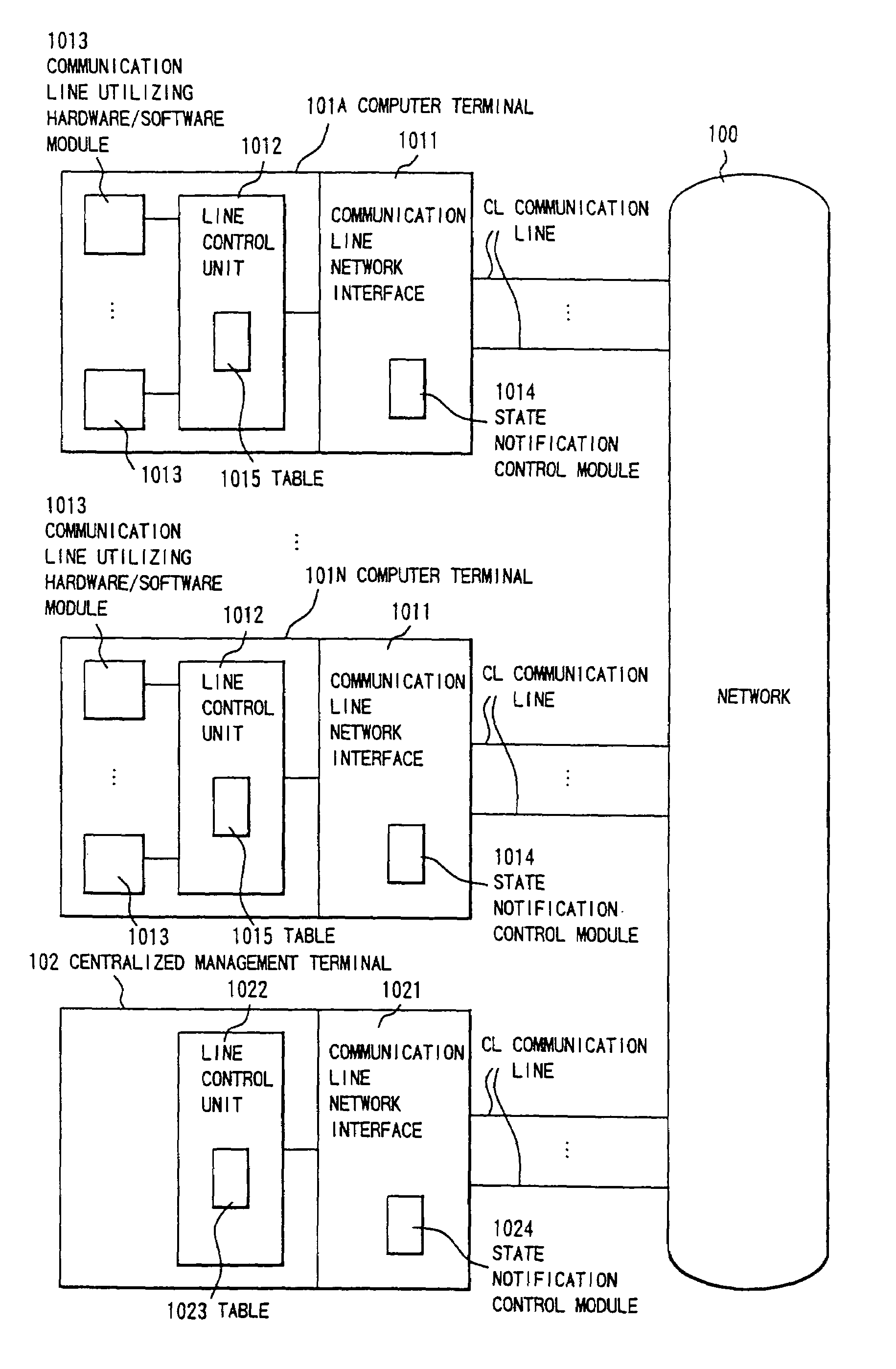
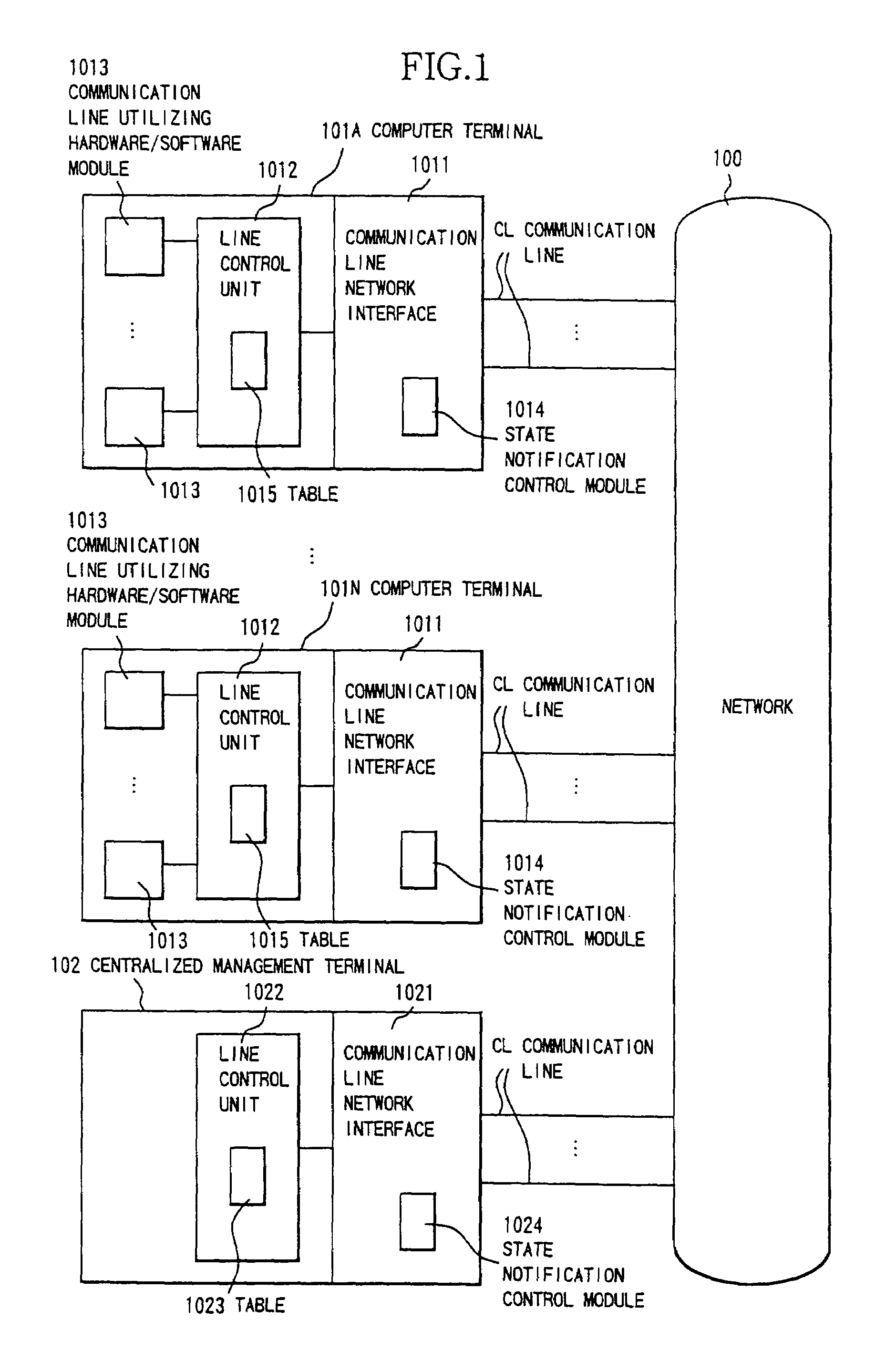
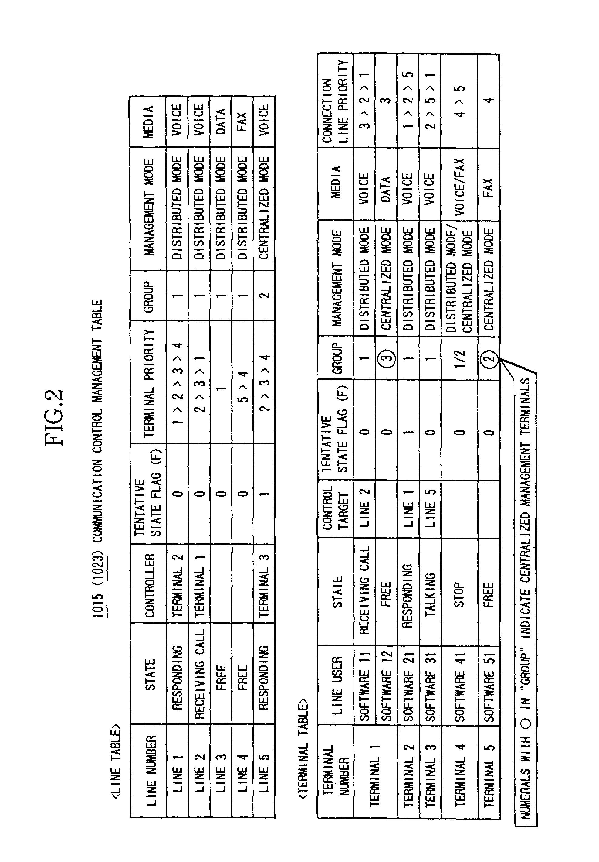
[0044]Referring to FIGS. 1, 2 and 3 in combination, the plurality of communication lines CL are connected to each computer terminal 101. When the communications (calls) occur at the same time on the plurality of lines, a specified communication line utilizing hardware / software module (a communication line utilizing application) 1013 determines a control target line on the basis of conditions (a priority of every line number, media information, and a category of the communication line utilizing software in boot) within the communication control management table 1015 defined as a preset condition table in the line control unit 1012 of the computer terminal 101, and only this hardware / software module 1013 is notified of a state of the line.

[0045]Further, with respect to a control request (the call response, etc.) given from the hardwa...

operational example 2

[0052]Next, referring to FIGS. 1, 2 and 4 in combination, in a case where the communication occurs on one arbitrary line CL and this line CL is controllable by a plurality of computer terminals 101, a control-assigned computer terminal 101 among the plurality of computer terminals 101 is determined based on conditions (the priorities given to the respective terminals with respect to that line, the media information and states of the terminals) in the preset table (any one of the tables 1015 and 1023 may be chosen) in the line control unit (any one of the units 1012 and 1022 may be selected), and only the thus determined computer terminal 101 is notified of a state of the communication.

[0053]Further, the control oriented to the network 100 is also effected by a combination of the above-determined computer terminal 101 and the control target line. The communication line utilizing hardware / software module 1013 executes the respective processes (the response request, the disconnection r...

operational example 3

[0060]Next, an operational example 3 will be explained referring to FIGS. 1, 2 and 5 in combination. In the operational examples 1 and 2 described above, in cases where the control-assigned communication line utilizing hardware / software module 1013 transfers the call to other terminal and where the control is transferred to other communication line utilizing hardware / software module 1013 (which is irrespective of belonging to the self-terminal or other terminal in this case) for the reason of an impossible-of-response state in the self-terminal (such as when the software comes to an end), the line control unit (1012 or 1022) is notified of a change instate.

[0061]Further, when becoming the controllable state, similarly, the line control unit (1012 or 1022) is notified of the change in state. With this notification, the line control unit (1012 or 1022) rewrites the table (1015 or 1023) and dynamically changes the line control with respect to the control assigned computer terminal.

[006...


PUM


Abstract

A communication line control system and a communication line control method have an architecture, in which if a plurality of calls that should be processed simultaneously occur in one communication terminal incorporating communication functions containing voice communications and data communications and accommodating a plurality of communication lines, a distributed control module utilizing the plurality of communication lines on this communication terminal processes only a specified call among the plurality of calls on the basis of condition data preset in a line control unit without being aware of the plurality of communication lines. With this architecture, it is feasible to enhance a general-purposed characteristic and a simplicity of creation of the software (distributed control module) for controlling the plurality of communication lines, reduce a load thereof and improve its usability.

Description

BACKGROUND OF THE INVENTION[0001]The present invention relates to a communication line control system including a plurality of communication terminals (communication terminal devices) each incorporating communication functions containing voice communications and data (facsimile) communications and accommodating a plurality of communication lines connected to a network. The present invention relates also to a communication line control method of controlling the plurality of communication lines in one single communication terminal, and of processing a communication on the same communication line between the plurality of communication terminals.[0002]With diversified needs, there have been provided services for making a plurality of communication lines controllable in one single communication terminal. For example, when telephone calls occur simultaneously, an arbitrary call can be responded by allocating the line per button in a telephone terminal connected to a button telephone syste...

Claims


Application Information

Patent Timeline
Patent Type & Authority Patents(United States)
IPC IPC(8): H04J3/16H04L12/50H04M3/00H04L69/14H04M3/42H04M7/00H04M11/00
CPCH04M3/42314H04M7/006
Inventor OHSAWA, NORIYUKIKITAGAWA, ISAMUSAKATA, MUNETAKA
Owner FUJITSU LTD
Why Eureka
Try Eureka