Rotor for a steam turbine

a technology for steam turbines and rotors, which is applied in the direction of machines/engines, mechanical equipment, liquid fuel engines, etc., can solve the problems of frequent physical design limits, reduce the effort to provide the rotor-internal cooling channel system, and improve heat transfer. , the effect of reducing the effor

Active Publication Date: 2007-09-11
GENERAL ELECTRIC TECH GMBH
View PDF11 Cites 20 Cited by
  • Summary
  • Abstract
  • Description
  • Claims
  • Application Information

AI Technical Summary

Benefits of technology

[0010]An object of the present invention is to provide an improved embodiment for a rotor of a steam turbine of the type mentioned initially that allows sufficient cooling of the respective cooling zone of the rotor, in particular of the rotor interior, with reduced production effort.
[0011]The present invention provides a rotor whose rotor parts have a depression on each of the end faces in order to produce the welding joint and which together form a cavity which is surrounded by the weld zone in the welded state, the cavity being integrated into the cooling channel system. This measure allows the cavity or the depressions which have been mentioned to be used before the welding of the rotor parts to incorporate the cooling channel or channels and / or the inlet flow channel or channels and / or the outlet flow channel or channels in the respective rotor part. There is therefore no need for any additional recesses, which on the one hand lead to weakening of the material and on the other hand must be closed again. It is thus possible to reduce the effort to provide the rotor-internal cooling channel system. At the same time, the cavity provides a worthwhile double function, thus overall bringing the effort for formation of the welded joint and of the rotor into perspective.
[0013]The cooling effect of a bore system (cooling channel system) through which cooling steam flows is particularly high if a large number of small bores are used as cooling channels instead of one large bore, because the cooling channel wall on which the cooling steam acts is considerably larger. At the same time, the cross-sectional area of a cooling channel should be small in order to ensure that the cooling steam speed is high, and thus to improve the heat transfer, that is to say the cooling effect. The large number of cooling channels advantageously do not run at the center of the rotor, since a bore through the rotor center considerably weakens the strength of the rotor there. In the case of rotor sections with a large external diameter, the mechanical load at the rotor center is of particular importance owing to the rotor centrifugal force. It frequently represents a physical design limit. Owing to the cooling effect, the solution according to the invention increases the strength at the rotor center, and the physical design limits are shifted in the direction of higher temperatures of the working steam and of a larger rotor diameter.
[0014]There are also particular advantages for a rotor which is produced from at least three rotor parts and accordingly has two weld zones as well as two cavities. The two cavities can be connected to one another by means of at least one cooling channel, while the at least one inlet flow channel ends at one cavity and the at least one outlet flow channel starts at the other cavity. With this design, the cavities effectively form nodes, which provide the communication between the at least one cooling channel and the at least one inlet flow channel on the one hand and the at least one outlet flow channel on the other hand. The linking of the at least one inlet flow channel and of the at least one outlet flow channel to one of the cavities in each case also makes it possible to form the at least one cooling channel only in the central rotor part of the three rotor parts, thus reducing the complexity for provision of the cooling channel system.

Problems solved by technology

It frequently represents a physical design limit.

Method used


Image

  • Rotor for a steam turbine
  • Rotor for a steam turbine
  • Rotor for a steam turbine

Examples


Embodiment Construction

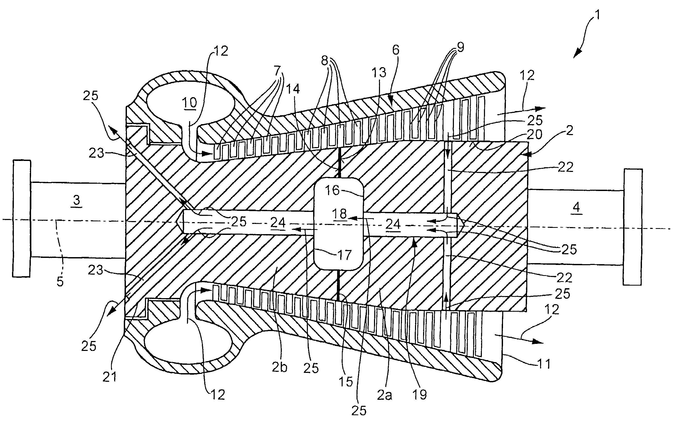
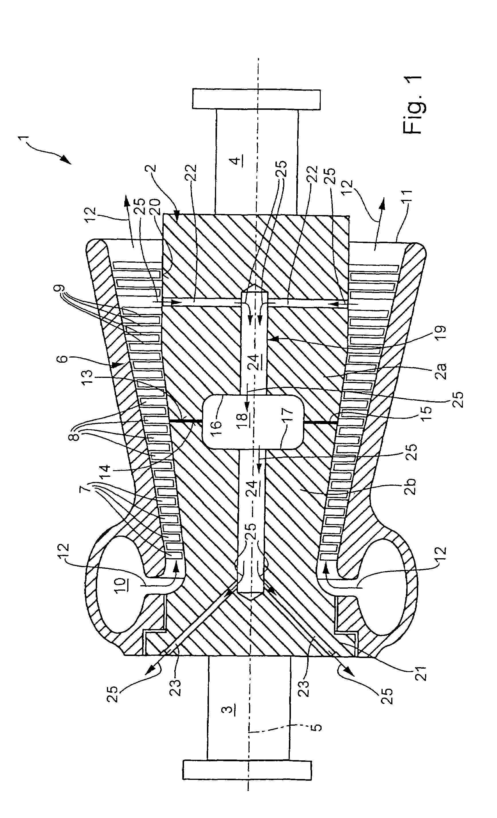
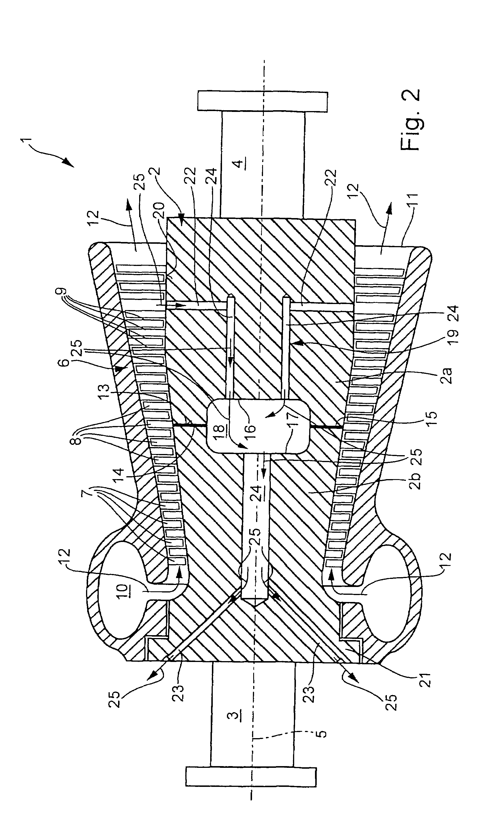
[0020]All of the figures illustrate only the inner housing and the rotor, but not the outer housing.

[0021]The invention will be explained in more detail in the following text with reference to exemplary embodiments and to FIGS. 1 to 9.

[0022]As is shown in FIG. 1, a steam turbine 1 has a rotor 2 which is mounted at its axial ends 3 and 4 such that it can rotate about a central rotation axis 5. The rotor 2 is arranged centrally in a housing 6, to which a number of stator blades 7 are fitted. Corresponding to this, the rotor 2 is fitted with a number of rotor blades 8, with the rotor blades 8 and the stator blades 7 forming, in pairs, the turbine stages 9 of the steam turbine 1. As is known, a steam turbine 1 operates with steam as the working medium, and this is also referred to as working steam. The housing 6 contains an inlet flow area 10, to which the compressed steam is supplied and from which the steam is passed to the first turbine stage 9 of the steam turbine 1. The expanded st...


PUM


Abstract

A rotor for a steam turbine for working steam and including at least two rotor parts welded to one another using a circumferential, annular weld zone, which is closed in the circumferential direction. A cooling channel system is formed in the rotor and has at least one inlet flow channel, at least one outlet flow channel and at least one cooling channel. In order to simplify the integration of the cooling channel system in the rotor, the weld zone surrounds a cavity which forms a component of the cooling channel system and through which cooling steam flows.

Description

[0001]Priority is claimed to German Patent Application No. DE 103 55 738.5, filed on Nov. 28, 2003, the entire disclosure of which is incorporated by reference herein.[0002]The present invention relates generally to steam turbines and more particularly to a rotor for a steam turbine for working steam and having a cooling channel formed in the rotor.BACKGROUND[0003]A rotor such as this for a steam turbine is known, for example, from EP 0 991 850 B1, extends along a rotation axis, and comprises at least two rotor parts which are adjacent to one another in the axial direction. In this case, the two rotor parts are welded to one another on mutually facing axial end faces by means of a circumferential, annular weld zone which is closed in the circumferential direction. A cooling channel system is formed in the rotor and has at least one inlet flow channel, at least one outlet flow channel and a cooling channel. The cooling channel carries cooling steam from at least one inlet flow channe...

Claims


Application Information

Patent Timeline
Patent Type & Authority Patents(United States)
IPC IPC(8): F01D5/14F01D5/06F01D5/08
CPCF01D5/063F01D5/085F01D5/087F01D5/088F05D2260/2322F05D2260/20F05D2260/205
Inventor HIEGEMANN, MICHAELREIGL, MARTIN
Owner GENERAL ELECTRIC TECH GMBH
Why Eureka
Try Eureka