Method and system for fabricating three-dimensional microstructure

a three-dimensional microstructure and microstructure technology, applied in manufacturing tools, heat treatment equipment, coatings, etc., can solve the problems of many limitations, difficult control of submicrometer to nanometer order, and limited use of photocurable resins, so as to reduce the effect of variations in etching rate and deposition ra

Active Publication Date: 2007-09-11
HITACHI HIGH TECH SCI CORP
View PDF4 Cites 10 Cited by
  • Summary
  • Abstract
  • Description
  • Claims
  • Application Information

AI Technical Summary

Benefits of technology

[0006]It is an object of the present invention to provide a method of creating a three-dimensional microstructure close to a designed shape, using a focused charged-particle beam, by alleviating the effects of var

Problems solved by technology

It is difficult to provide controls on the submicrometer to nanometer order.
Furthermore, the usable materials are limited to photocurable resins.
In this way, there are many limitations.
However, with the above-described prior art method, it is difficult to accura

Method used


Image

  • Method and system for fabricating three-dimensional microstructure
  • Method and system for fabricating three-dimensional microstructure
  • Method and system for fabricating three-dimensional microstructure

Examples


embodiment 1

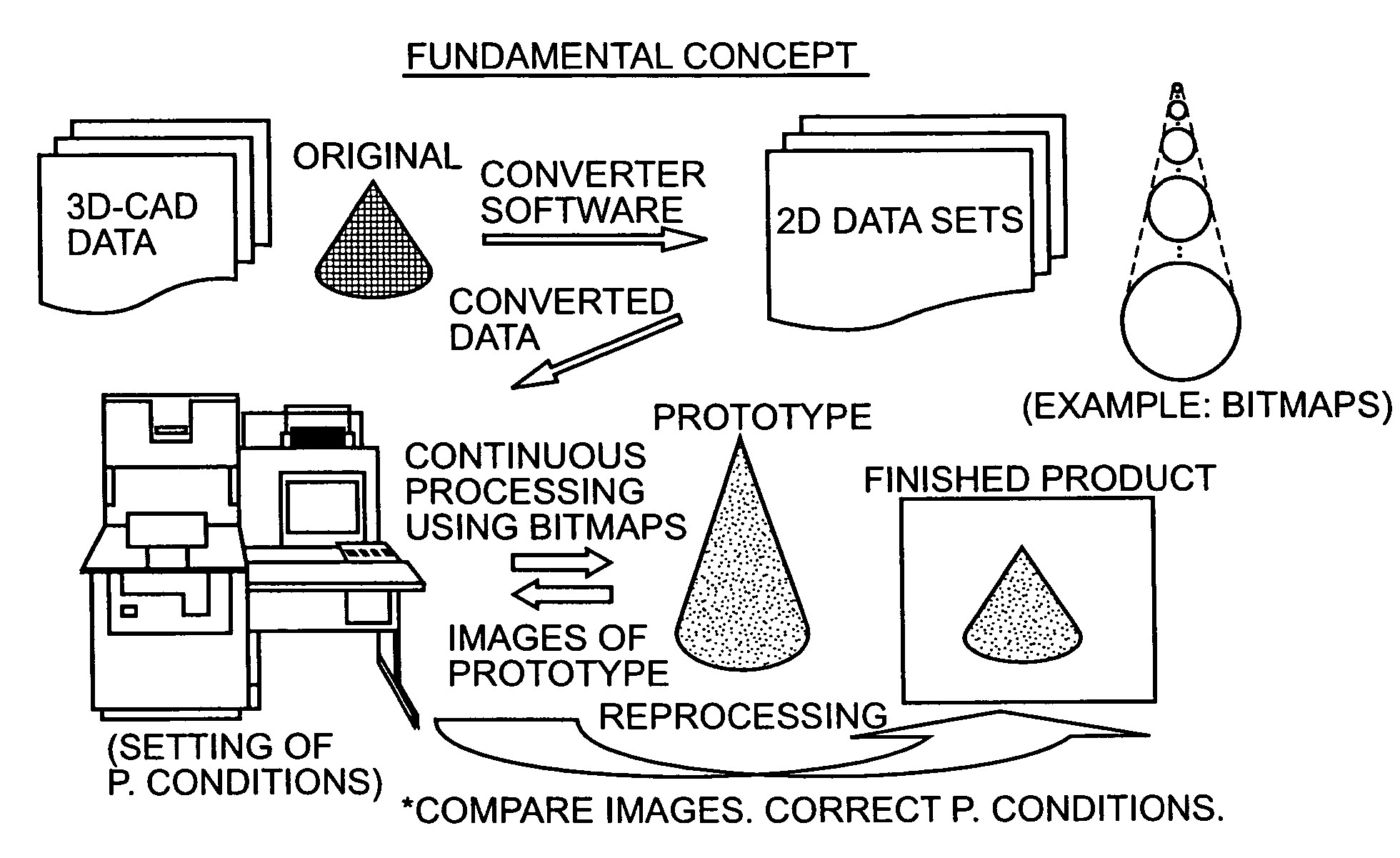
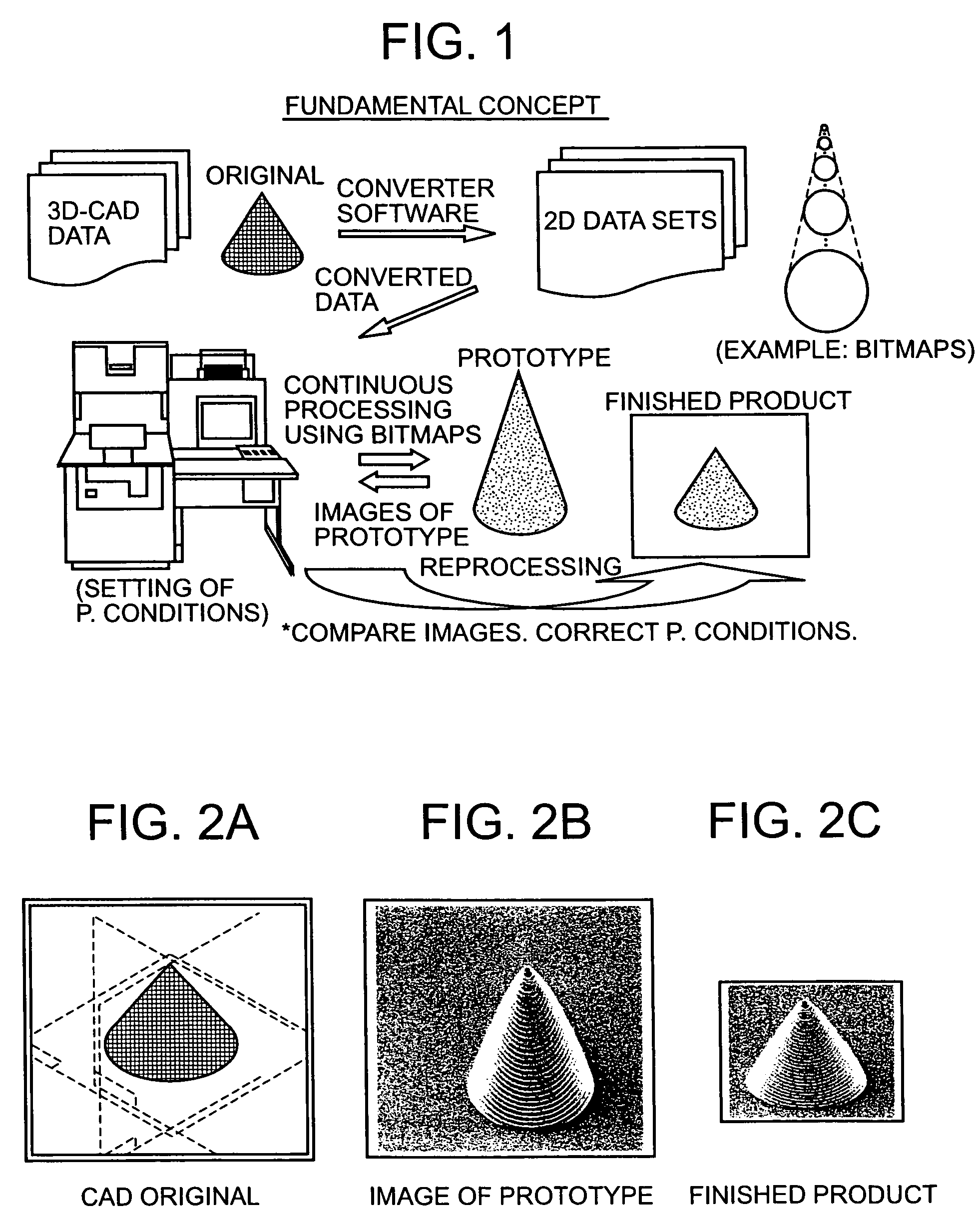
[0023]A fabrication system according to the invention is described by referring to FIG. 9. This system has an FIB machine body, a scanning electron microscope column 8, a computer 10 for creating and sending control signals to the FIB machine body and to the scanning electron microscope, a display unit 11, and a CAD system 12. The FIB machine body consists of an ion source 1, an ion optical system 3, a deflector 4, a secondary charged-particle detector 5, gas guns 6, and a sample stage 7 fitted with a five-axis drive mechanism. Operations for converting information about the dimensions of a three-dimensional microstructure to be fabricated into a number of two-dimensional shapes are performed by the CAD system 12. The converted data are sent to the computer 10. At this time, it is assumed that a model indicated by the CAD information is a conic structure as shown in FIG. 2A, for example. To fabricate this structure, a deposition creation mode using CVD is selected in the present emb...


PUM

PropertyMeasurementUnit
Microstructureaaaaaaaaaa
Acceleration voltageaaaaaaaaaa

Abstract

A method of fabricating a three-dimensional microstructure provides data corresponding to information relating to the structure of a three-dimensional microstructure design. A sample is processed in accordance with the provided data by irradiating the sample with a charged-particle beam while controlling processing conditions of the charged-particle beam. Dimensions of the processed sample are compared with the provided data to identify differences between the structure of the processed sample and the structure of the three-dimensional microstructure design. The sample is then irradiated again with a charged-particle beam to correct the identified structural differences while adjusting the processing conditions of the charged-particle beam to thereby fabricate a three-dimensional microstructure having a structure substantially the same as the structure of the three-dimensional microstructure design.

Description

BACKGROUND OF THE INVENTION[0001]1. Field of the Invention[0002]The present invention relates to techniques for forming a three-dimensional microstructure by (i) a CVD process consisting of irradiating a sample surface with a focused ion beam or electron beam while blowing a source gas against the surface, (ii) an etching process consisting of irradiating a sample surface with a focused ion beam, or (iii) another etching process consisting of irradiating a sample surface with a focused ion beam or electron beam while blowing an etchant gas against the surface.[0003]2. Description of Related Art[0004]So-called microstereolithography making use of photopolymerization reactions using a synthetic resin material is known as a technique for creating a three-dimensional microstructure. With this method, however, only structures having sizes on the micrometer order or greater can be fabricated. It is difficult to provide controls on the submicrometer to nanometer order. Furthermore, the usa...

Claims


Application Information

Patent Timeline
IPC IPC(8): C21D1/54B81C99/00C23C16/04C23C16/48H01J37/302
CPCC23C16/047H01J37/3023H01J2237/30411H01J2237/31737H01J2237/3174H01J2237/31749B33Y50/02
Inventor IWASAKI, KOUJI
Owner HITACHI HIGH TECH SCI CORP
Why Eureka
Try Eureka