Method and apparatus for digital synthesis of microwaves

a digital synthesis and microwave technology, applied in the direction of pulse train generators, pulse techniques, line-transmission details, etc., can solve problems such as multiple implementations, and achieve the effect of high efficiency

Active Publication Date: 2007-09-11
BAE SYST INFORMATION & ELECTRONICS SYST INTERGRATION INC
View PDF16 Cites 27 Cited by
  • Summary
  • Abstract
  • Description
  • Claims
  • Application Information

AI Technical Summary

Benefits of technology

[0018]According to the present invention to form a three conductor system, conductor segments are positioned within a two conductor transmission line in order to generate microwave pulses. This allows the conductor segments to be switchably coupled to one or the other of the transmission lines. Thus, unlike the prior art, microwave pulses are induced from a series of conductive segments into uninterrupted transmission lines which carry the signal in a desired direction. The signal does not have to propagate through more than one closed switch, and thus more pulses may be synthesized in a pulse train with higher efficiency. This arrangement is susceptible to multiple implementations.
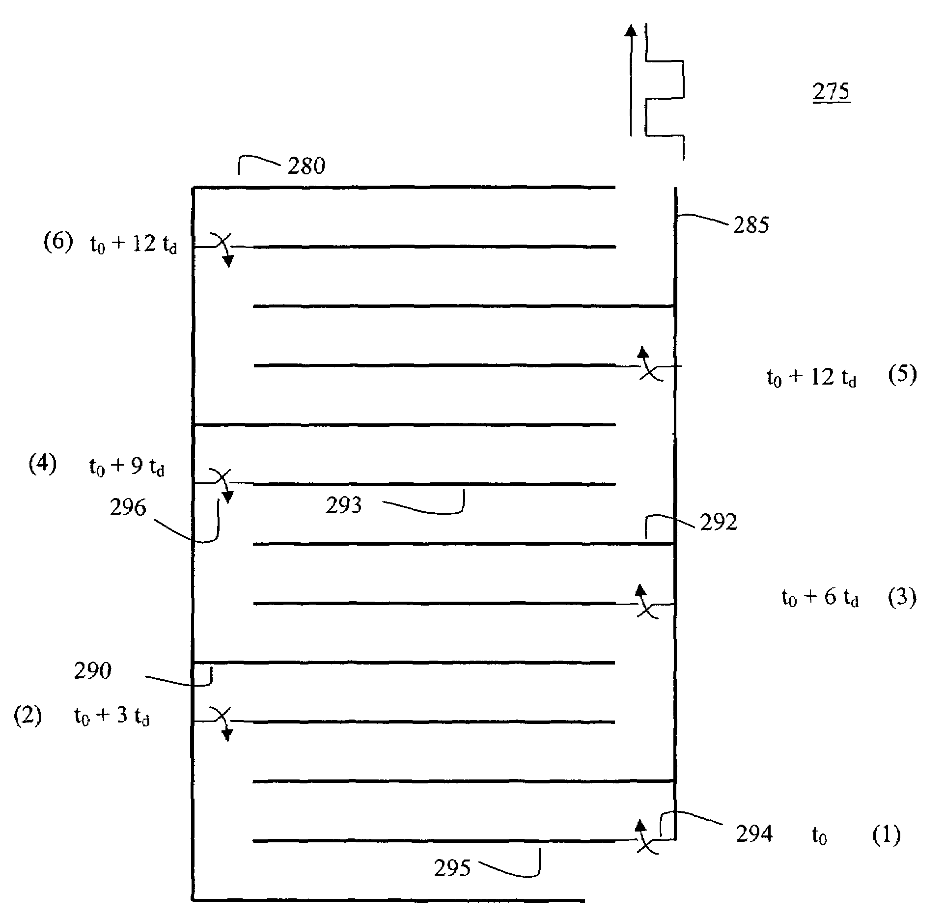
[0019]For example, according to one embodiment of the invention, each conductor segment may be charged to a different polarity and / or voltage as compared to the conductor segment on either side of it. In this implementation, all of the conductive segments are coupled through switches to one of the transmission line conductors. In this arrangement, the switches may be closed by any stimulation technique to produce a pulse train. According to one embodiment, the apparatus functions by sequentially activating switches from back to front along the pair of transmission lines, thereby discharging the segments (each charged to a selected voltage) in series into the continuous transmission lines. Appropriate timing of the closing of the switches is used to create a microwave signal having desired properties, high power and high frequency. Because the switches are placed in parallel with the transmission line during wave propagation, lower quality switches may be used. Higher quality switches, such as LASS switches, may be used to give higher power and precise control of the signal and to allow coherence between multiple such sources to facilitate the creation of a phased array system. The power of the pulse generated by such a system may be high, for example a 100 kV 50 ohm system may produce a 50 MW pulse. A 10 kV, 0.1 ohm system may produce a 250 MW pulse. An adiabatic transformer may be used to provide coupling to an antenna. In principle, the system is simple and allows compact design.
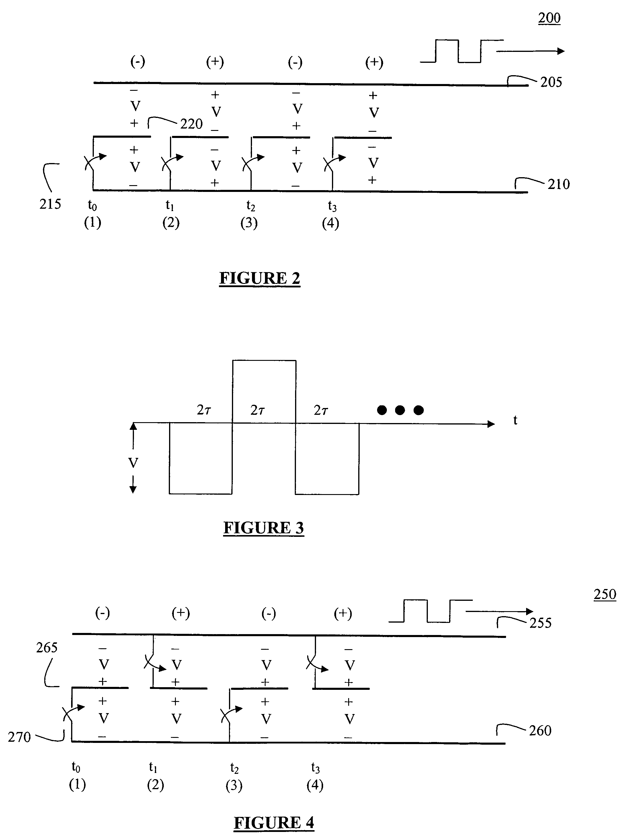
[0020]According to another embodiment, the conductive segments may be charged to the same voltage potential and the switches associated with each conductive segment may be coupled to opposite ones of the transmission line conductors in an alternating fashion. In this arrangement, the switches may be closed by any stimulation technique to produce different pulse trains. According to one embodiment, the apparatus functions by sequentially activating switches from back to front along the pair of transmission lines, thereby discharging the segments (each charged to a selected voltage) in series into the continuous transmission lines. Appropriate timing of the closing of the switches is used to create a microwave signal, a pulse train, having high power and high frequency.

Problems solved by technology

This arrangement is susceptible to multiple implementations.

Method used


Image

  • Method and apparatus for digital synthesis of microwaves
  • Method and apparatus for digital synthesis of microwaves
  • Method and apparatus for digital synthesis of microwaves

Examples


Embodiment Construction

[0035]According to the present invention, transmission line conductor segments are positioned within a three conductor transmission line in order to generate microwave pulses. This allows the conductor segments to be switchably coupled to one or the other. Thus, unlike the prior art, microwave pulses are induced from a series of conductive segments into uninterrupted transmission lines, which carry the signal in a desired direction. The signal does not have to propagate in the desired direction through more than one closed switch, and thus longer and more powerful pulse trains may be produced. This arrangement is susceptible to multiple implementations.

[0036]FIG. 2 depicts a digital synthesis transmission line structure 200 that generates microwave pulses according to an embodiment of the present invention. Referring to FIG. 2, the digital synthesis transmission line 200 includes two conductors 205 and 210 on either side of a plurality of center transmission line segments 220. These...


PUM


Abstract

Conductor segments are positioned within a two conductor transmission line in order to generate microwave pulses. The conductor segments are switchably coupled to one or the other of the transmission lines in parallel. Microwave pulses may be induced in the transmission line by closing the switches in a controlled manner to discharge successive segments into the transmission lines. The induced waves travel uninterrupted along the transmission lines in a desired direction.

Description

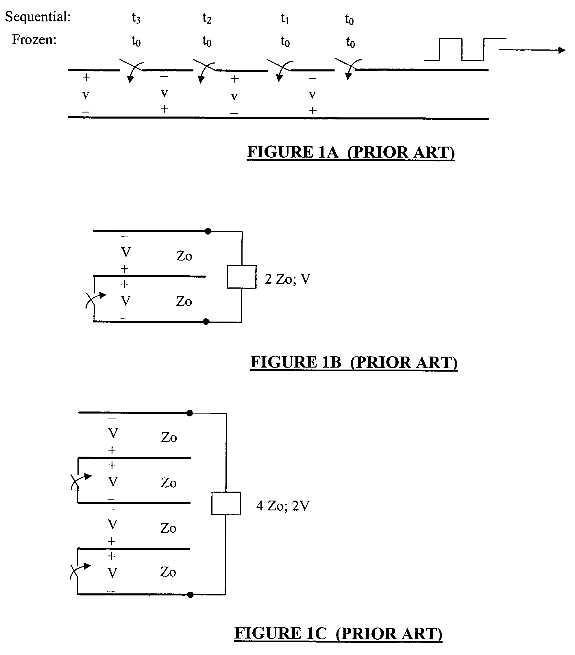
FIELD OF THE INVENTION[0001]The present invention relates to a method and apparatus for generating microwaves and more particularly to a microwave source and a method for generating microwaves by digital synthesis.BACKGROUND OF THE INVENTION[0002]Digital synthesis of microwaves uses transmission lines and switches to generate a series of alternating polarity pulses. The coupling of the resulting pulse train to a load such as an antenna results in the radiation of a short microwave pulse. This approach has been investigated for over 30 years.[0003]The general concept of producing microwaves by a sequential operation of switches is well known. High peak power microwave generation is addressed by Driver et al. in U.S. Pat. No. 4,176,295 in which the generation of microwaves by periodically discharging a plurality of identical, direct current energized, resonant transmission lines into a TE wave guide at half-multiple wavelength spacings is discussed. To periodically discharge the trans...

Claims


Application Information

Patent Timeline
Patent Type & Authority Patents(United States)
IPC IPC(8): H03K3/42
CPCH03B11/02H03K3/53
Inventor ZUCKER, OVEDLONDON, SIMON Y.
Owner BAE SYST INFORMATION & ELECTRONICS SYST INTERGRATION INC
Why Eureka
Try Eureka