Method for forming radio frequency antenna

a radio frequency antenna and antenna body technology, applied in the field of radio frequency antennas, can solve the problems of unreliability and prone to failure, and achieve the effects of reducing the resistance between the electrode and the other locations on the conductive ink layer, and reducing the risk of failur

Inactive Publication Date: 2007-09-11
SQUARE 1 BANK
View PDF27 Cites 9 Cited by
  • Summary
  • Abstract
  • Description
  • Claims
  • Application Information

AI Technical Summary

Benefits of technology

[0011]The use of the electrical-short layer has the advantage that it allows the resistance between the electrode and the other locations on the conductive ink layer to be reduced. The electrical-short layer effectively results in a more uniform electroplating on all the points on the radio frequency coil pattern. This avoids the problem that occurred in the prior art of requiring a relatively thick conductive ink layer. In the method of the present invention, an effectively uniform conductive electroplate layer can be produced.

Problems solved by technology

This has the downside of it being unreliable and prone to failure during the operation of the radio frequency antenna.

Method used


Image

  • Method for forming radio frequency antenna
  • Method for forming radio frequency antenna
  • Method for forming radio frequency antenna

Examples


Embodiment Construction

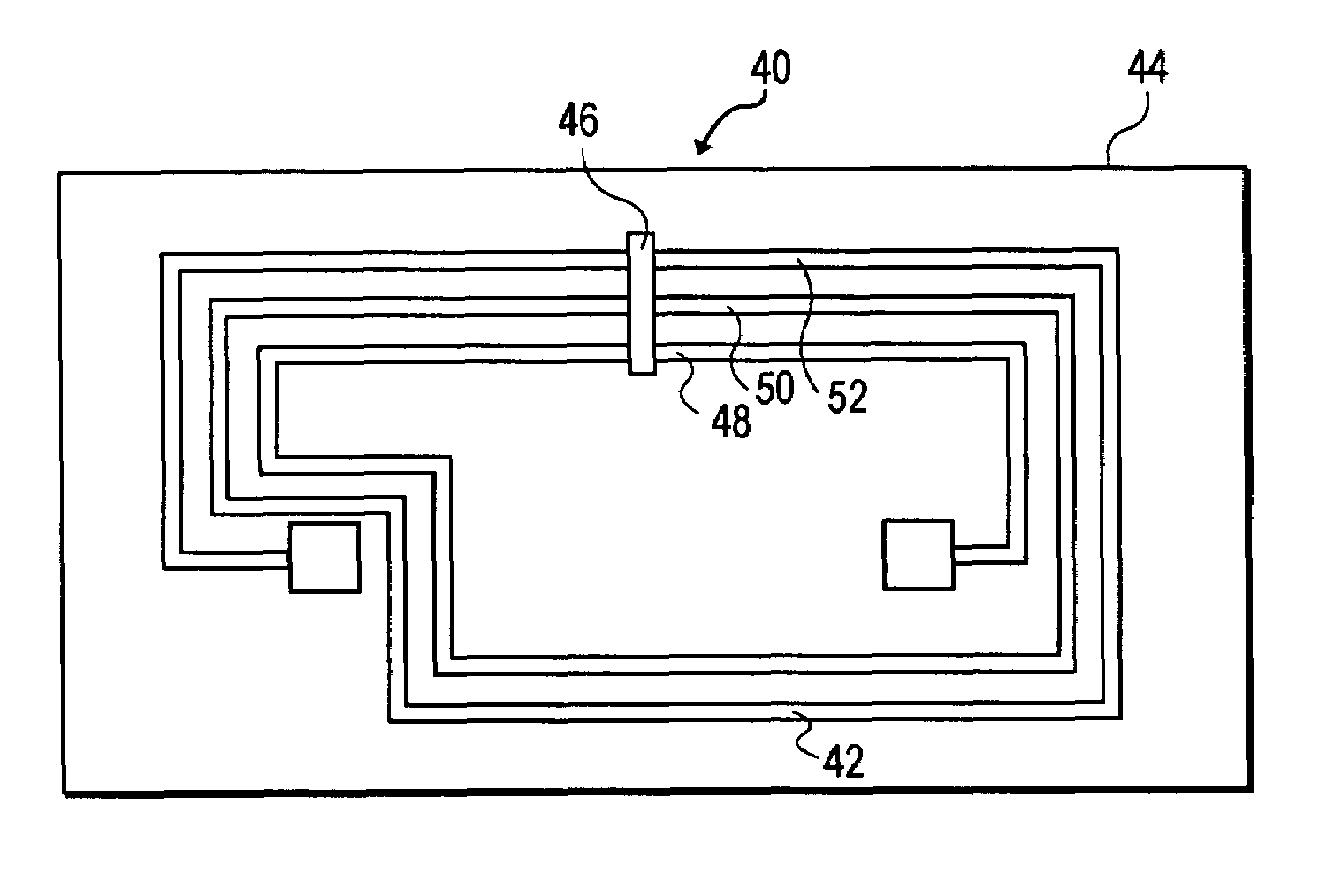
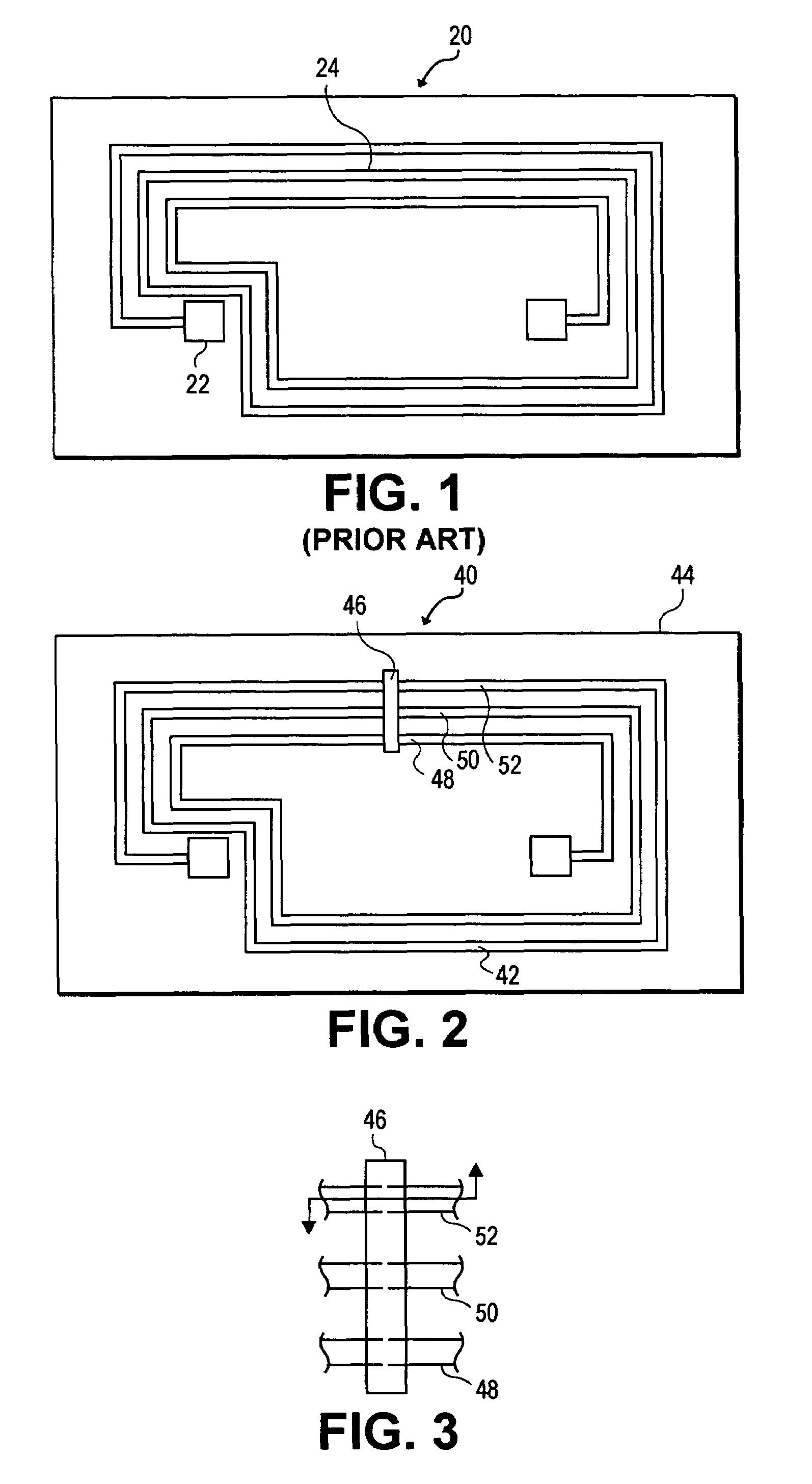
[0022]FIG. 2 is a top view of a radio frequency antenna 40 being constructed by the method of one embodiment of the present invention. The radio frequency antenna 40 includes a conductive ink pattern 42 formed in a coil on the substrate 44. An electrical-short layer 46 is formed over top of the conductive ink coil pattern, and preferably a nonconductive plating resist is formed over the short. The electrical-short layer 46 ensures that points 48, 50 and 52 on the conductive ink pattern 42 will have relatively similar voltages during the electroplating process. This means all locations on the conductive ink pattern 42 will be electroplated evenly. Thus the apparatus of the present invention allows for a conductive electroplate layer of sufficient thickness on all points of the radio frequency antenna.

[0023]The use of the electrical-short layer 46 allows for the use of a thinner and / or narrower conductive ink layer 42. The resistance of the conductive ink layer during the electroplate...


PUM

PropertyMeasurementUnit
conductiveaaaaaaaaaa
non-conductiveaaaaaaaaaa
electrical-aaaaaaaaaa

Abstract

A metalized circuit suitable for application as a radio frequency antenna is produced by forming an antenna coil pattern on a flexible substrate. The antenna coil pattern is formed using a conductive ink which is patterned on the substrate. The conductive ink is cured and an electrical-short layer is formed across the coils of the conductive ink pattern. An insulating layer is formed over top of the electrical-short layer, a metal layer electroplated on top of the conductive layer, and then the electrical-short layer is removed. The use of the electrical-short layer during the electroplating allows for the voltage at the different points on the conductive ink layer to be relatively similar, so that a uniform electroplate layer is formed on top of the conductive ink layer. This results in a better quality radio frequency antenna at a reduced cost.

Description

CLAIM OF PRIORITY[0001]This application is a continuation in part of U.S. patent application Ser. No. 10 / 238,598 filed Sep. 11, 2002, now U.S. Pat. No. 6,933,892, which is a continuation of U.S. patent application Ser. No. 09 / 524,505 filed Mar. 13, 2000, now U.S. Pat. No. 6,476,775.BACKGROUND OF THE INVENTION[0002]The present invention relates to methods of manufacture of flexible circuits used in construction of radio frequency (RF) antennae.[0003]Radio frequency antennae are typically made in a conductive coil pattern. The conductive coil pattern allows the antenna to receive and radiate energies in the radio frequency range. Typically, the antenna is optimized to transmit and receive energy in a relatively narrow portion of the radio frequency range.[0004]Radio frequency antennae are used in a number of different areas including inventory control. Often the radio frequency antenna is connected to an integrated circuit. The integrated circuit receives energy from a detector unit, ...

Claims


Application Information

Patent Timeline
Patent Type & Authority Patents(United States)
IPC IPC(8): H01Q7/00H01Q1/22H01Q1/38H01Q9/27H05K1/09H05K1/16H05K3/24
CPCH01Q1/22H01Q1/2225H01Q1/38H01Q7/00H01Q9/27H05K3/242H05K1/0393H05K1/095H05K1/165H05K3/245H05K3/246H05K2201/0347H05K2203/0191H05K2203/0769H05K2203/1476H05K2203/1545H05K2203/173H05K2203/175
Inventor OBERLE, ROBERT R.
Owner SQUARE 1 BANK
Why Eureka
Try Eureka