
Combined absolute-pressure and relative-pressure sensor

a technology of absolute pressure and relative pressure, which is applied in the field of micromechanical pressure sensors, can solve the problems of the possibility of conducting safety checks and plausibility checks of obtained data, and achieve the effects of reducing costs, increasing reliability, and high potential

Inactive Publication Date: 2007-09-18
ROBERT BOSCH GMBH
View PDF12 Cites 14 Cited by
  • Summary
  • Abstract
  • Description
  • Claims
  • Application Information

AI Technical Summary

Benefits of technology

This integrated solution enhances measurement accuracy, reduces costs, and improves reliability by eliminating measurement inaccuracies from separate sensor locations and temperatures, while allowing for space and cost savings by replacing two individual sensors with a single chip solution.

Problems solved by technology

Thus, in safety-related applications, there is the possibility of conducting safety checks and plausibility checks of the obtained data.

Method used


Image

  • Combined absolute-pressure and relative-pressure sensor
  • Combined absolute-pressure and relative-pressure sensor

Examples


Embodiment Construction

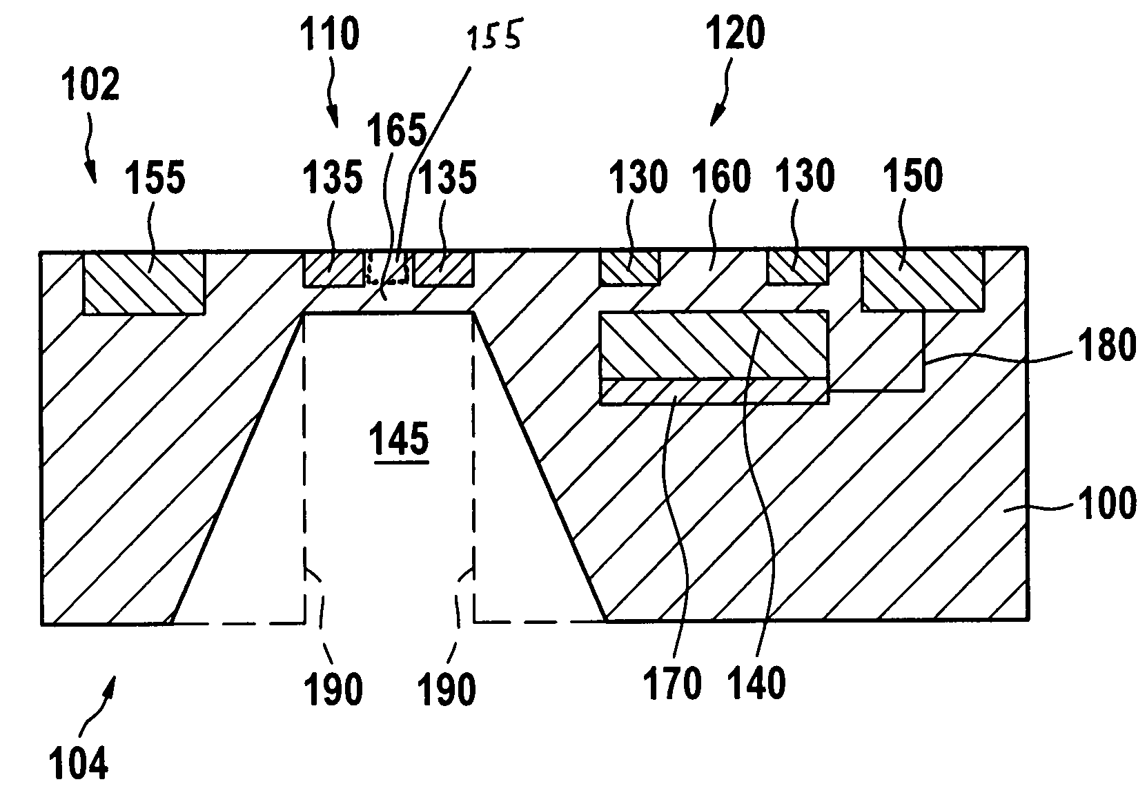
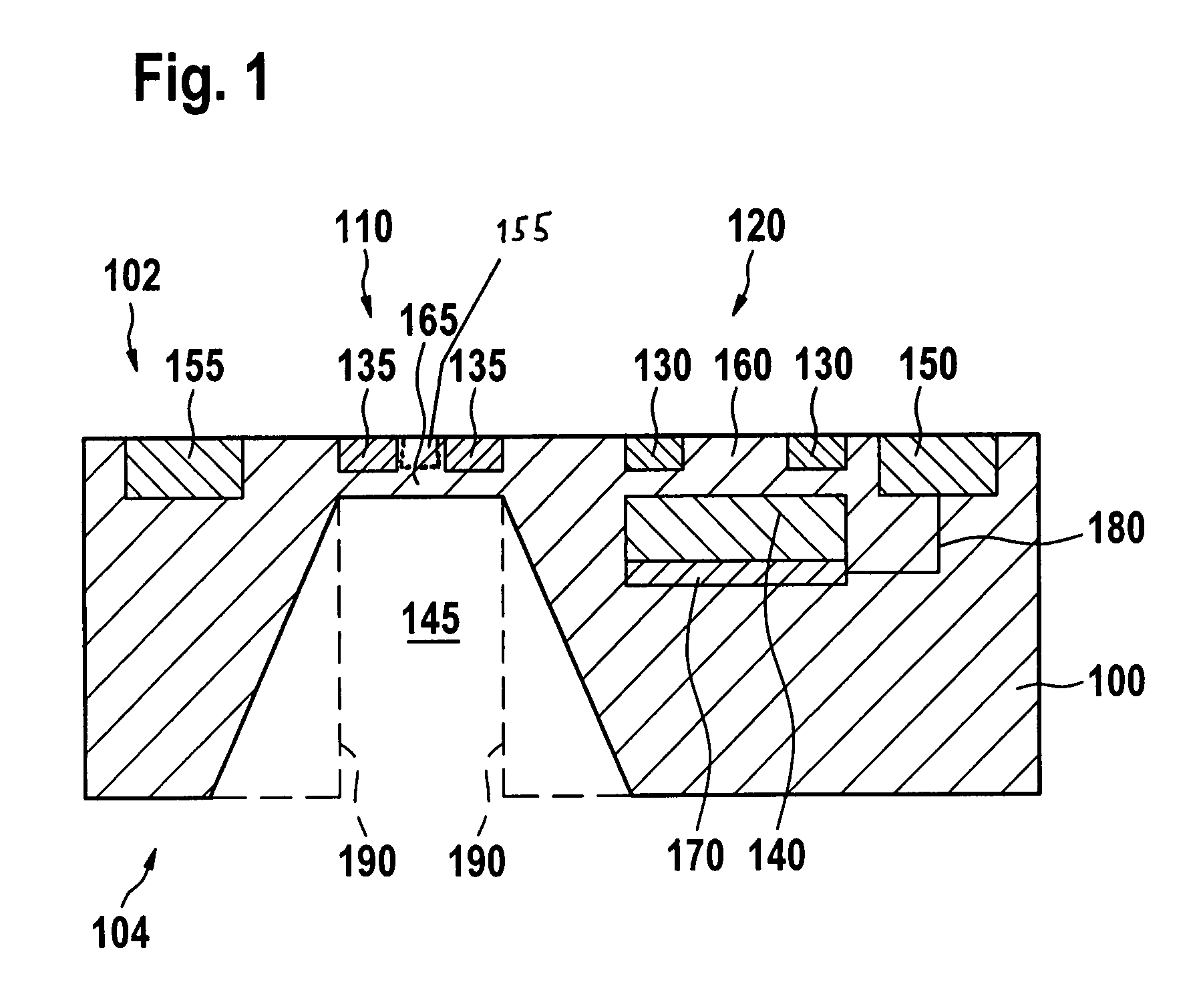
[0014]In FIG. 1, a combination of an absolute-pressure sensor 120 and a relative-pressure sensor 110 according to the present invention is illustrated, using a specific exemplary embodiment. In this context, the sensor elements, which are required for measuring the two pressure variables, have been produced in or on a common substrate 100. Since it is already known from the related art, that a relative-pressure sensor or differential-pressure sensor 110 can be produced from a semiconductor substrate 100 in the same way as an absolute-pressure sensor 120, using micromechanical manufacturing processes, only the special features of the combination of the two pressure sensors will be discussed in the following description. For the standard production of an absolute-pressure sensor and a relative-pressure sensor by micromechanical manufacturing processes, reference is made to the related art mentioned above.

[0015]As is evident from FIG. 1, relative-pressure sensor 110 is made up of a dia...


PUM

PropertyMeasurementUnit
pressureaaaaaaaaaa
absolute-pressure variableaaaaaaaaaa
relative-pressure variableaaaaaaaaaa

Abstract

A micromechanical sensor for measuring at least a first pressure of a first medium, as well as a method for manufacturing such a micromechanical sensor. The micromechanical sensor has at least one substrate having at least two sensor elements, which are preferably made of a semiconductive material. The substrate has at least a first sensor element for measuring an absolute-pressure variable of the first medium and a second sensor element for measuring a relative-pressure variable of the first medium.

Description

FIELD OF THE INVENTION[0001]The present invention relates to a micromechanical pressure sensor and a method for manufacturing a micromechanical pressure sensor, where a substrate has at least two sensor elements for measuring pressure.BACKGROUND INFORMATION[0002]German Patent Application No. DE 42 27 893 describes a differential-pressure sensor, which has two semiconductor diaphragms. The semiconductor diaphragms are each provided with interconnected piezoresistive resistors on the upper side. To protect the sensitive sensor elements, the upper sides of the semiconductor diaphragms are situated in a common reference chamber, which can be hermetically sealed.[0003]In addition to the measurement of a differential pressure, the measurement of an absolute pressure with the aid of micromechanical pressure sensors is also known from the related art. Thus, for example, German Patent Application No. DE 100 32 579 describes the manufacture of such an absolute-pressure sensor, where a cavity ...

Claims


Application Information

Patent Timeline
Patent Type & Authority Patents(United States)
IPC IPC(8): G01L9/00G01L13/02G01L13/06H01L29/84
CPCG01L9/0042G01L9/0054G01L9/0073
Inventor VOSSENBERG, HEINZ-GEORG
Owner ROBERT BOSCH GMBH
Learn More