Decoupled planar positioning system

a planar positioning and decoupling technology, applied in the direction of electric/magnetic measurement arrangements, element comparison, manual actuation control mechanisms, etc., can solve the problems of increasing the cost of the system, affecting the positioning accuracy, and poor efficiency of the actuator power used for moving the payload, etc., to achieve excellent footprint efficiency, high speed, and high precision

Inactive Publication Date: 2007-09-18
AGENCY FOR SCI TECH & RES
View PDF12 Cites 16 Cited by
  • Summary
  • Abstract
  • Description
  • Claims
  • Application Information

AI Technical Summary

Benefits of technology

[0014]The decoupled planar positioning system disclosed herein uses novel design to provide high speed, high precision planar motion with excellent footprint efficiency and dynamic stiffness. Decoupling of the actuators that provide the orthogonal axes of motion means that none of the actuators is carrying the weight of the other actuators and hence improving the overall efficiency of the system. In addition, decoupling also means that the errors and dynamics of o...

Problems solved by technology

One significant drawback of this stacking approach is that the positioning accuracy is substantially affected by the errors in each of the individual actuator assemblies.
Since the actuator assemblies are coupled together, the errors of an actuator in every direction will all contribute to the overall positioning errors of the system.
Another disadvantage of stacked stages is the poor efficiency of the actuator power used for moving the payload.
This necessitates the use of higher capacity actuators to overcome the problem, thereby increasing the cost of the system.
Furthermore, the stacking approach reduces the overall rigidity of the system.
Whilst the conventional approach of stacking actuators has intrin...

Method used


Image

  • Decoupled planar positioning system
  • Decoupled planar positioning system
  • Decoupled planar positioning system

Examples


Embodiment Construction

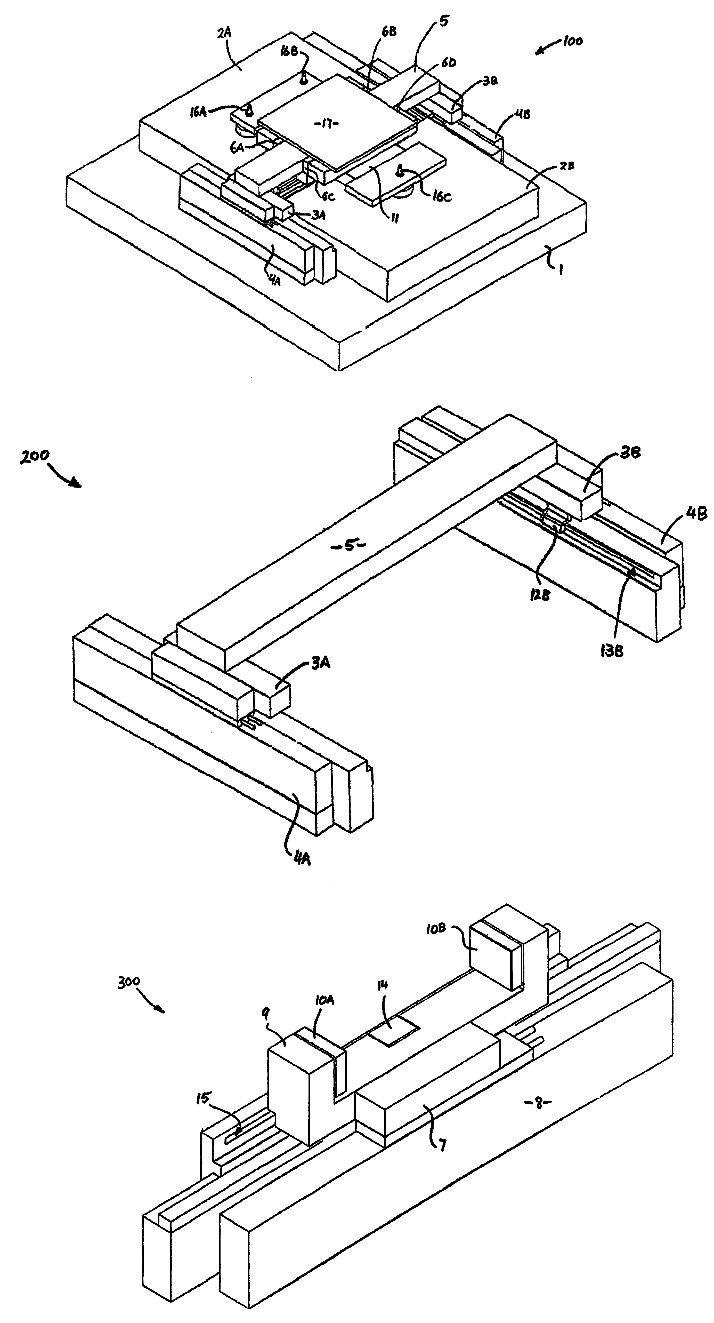
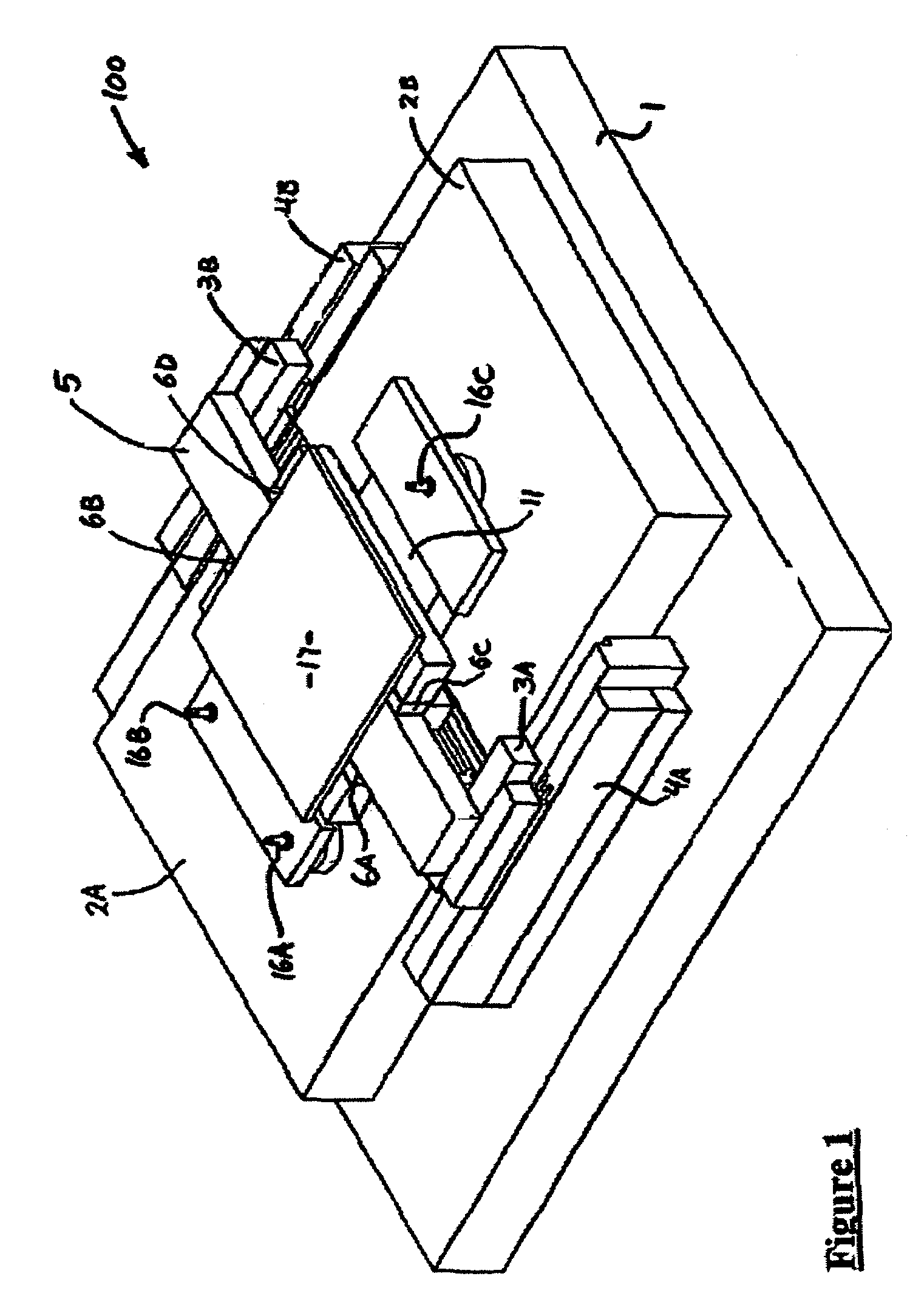
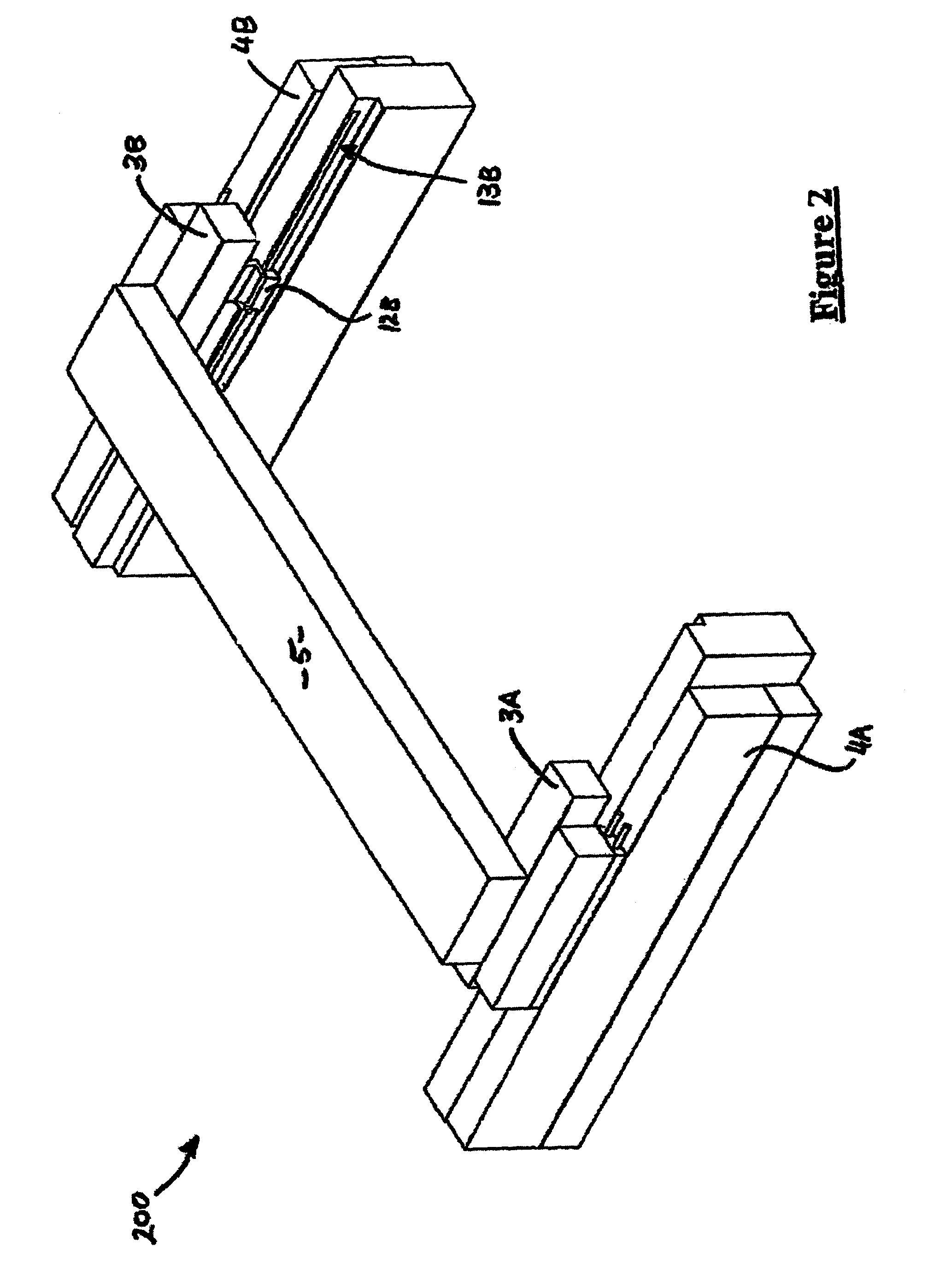
[0024]A decoupled planar positioning apparatus 100 is illustrated in the drawings, constructed according to a preferred embodiment of the present invention. The overall structure of the positioning apparatus 100 which is illustrated in FIG. 1 can be considered as a combination of several sub-assemblies, namely an X-axis assembly 200 shown in isolation in FIG. 2, a Y-axis assembly 300 shown in FIG. 3, and a planar platform assembly 400, shown in FIG. 4. The positioning apparatus 100 is also shown in FIG. 5 equipped with displacement measuring interferometer systems.

[0025]The structure of the positioning apparatus as shown in FIG. 1 includes a table top 1 and reference plates 2A and 2B. The reference plates 2A, 2B are similarly sized rectangular plates supported on an upper surface of the table top 1, and positioned adjacent one another with a gap between their adjacent edges. The two reference plates 2A and 2B are kinematically supported on the table top 1 at three location per plate...


PUM


Abstract

A planar positioning system having a rigid base, and first and second linear actuator means mounted to the rigid base, the first and second linear actuator means being arranged orthogonal to one another. A rigid reference surface (2A, 2B) is mounted to the base, (1) and a moveable platform (17) for holding a workpiece is supported for movement on the rigid reference surface (2A, 2B). First and second guiding means are coupled to moveable portions of the respective first and second actuator means, the first and second guiding means being arranged to bear on the moveable platform for transmission of forces thereto from the respective first and second actuator means to effect movement of the platform (17) on said rigid reference surface (2A, 2B). The first actuator means may comprise two linear actuators (4A, 4B) parallel to one another and spaced apart with the second linear actuator means (8) orthogonal thereto and arranged in an H-shaped configuration. The first and second guiding means and/or the components of the moveable platform (17) against which they bear are preferably constructed for low frictional movement in the direction orthogonal to the transmission of forces therefrom, such as by the use of non-contact aerostatic bearings (16A, 16B, 16C) or the like. Similarly, low friction bearings are utilised between the moveable platform (17) and the reference surface (2A, 2B).

Description

FIELD OF THE INVENTION[0001]This invention relates to an electromechanical planar positioning system which enables high-precision, high-payload positioning of workpieces such as integrated circuit wafers, photonic components, micro-electromechanical systems and the like.BACKGROUND OF THE INVENTION[0002]A conventional XY planar positioning system stacks an X-actuator assembly onto a Y-actuator assembly to form the two orthogonal axes. One significant drawback of this stacking approach is that the positioning accuracy is substantially affected by the errors in each of the individual actuator assemblies. Since the actuator assemblies are coupled together, the errors of an actuator in every direction will all contribute to the overall positioning errors of the system.[0003]Another disadvantage of stacked stages is the poor efficiency of the actuator power used for moving the payload. In such a system an actuator is required to move not only the payload but also the mass of the other act...

Claims


Application Information

Patent Timeline
IPC IPC(8): G03F7/20H02K41/03B23Q1/01B23Q1/38B23Q1/62B23Q5/28H01L21/68
CPCB23Q1/012B23Q1/38B23Q1/621B23Q17/2495B23Q5/28Y10T74/20207H01L21/68
Inventor LIM, SER YONGLIN, WEILEOW, YONG PENG
Owner AGENCY FOR SCI TECH & RES
Why Eureka
Try Eureka