
Micro-oscillating member, light-deflector, and image-forming apparatus

a micro-oscillating member and light-deflector technology, applied in piezoelectric/electrostrictive/magnetostrictive devices, instruments, optics, etc., can solve the problem that the type light-deflector cannot fully obtain the maximum usable deflection angle sub, and the angular velocity is not constan

Inactive Publication Date: 2007-09-18
CANON KK
View PDF21 Cites 50 Cited by
  • Summary
  • Abstract
  • Description
  • Claims
  • Application Information

AI Technical Summary

Benefits of technology

This solution stabilizes angular velocity fluctuations, increases the effective deflection angle and time, simplifies assembly, reduces dynamic flexure, and enables miniaturization while maintaining image quality, thereby improving scanning efficiency and reducing power consumption in image-forming apparatuses like laser beam printers.

Problems solved by technology

In the meantime, in the resonance type reflector, there is a problem that, since a scanning angle of the mirror changes in sine-wise in principle, an angular velocity is not constant.
However, the arcsin lens has a problem in that the size of a beam spot of the laser light on the photosensitive body changes at the time of the optical scanning correction.
In this way, there is a problem that the conventional resonance type light deflector is unable to fully obtain the maximum usable deflection angle θeff and the effective time teff as large values.
Further, there is a problem that, since the resonance type deflector has the same angular velocity in moving back and forth, when making a single side scanning, the time effectively acquired for the scanning becomes short.
Further, there is a problem that, when a plurality of deflectors are used for correcting these problems, the structure becomes complicated.
Further, there is a problem that since the mirror has to maintain a desired flatness even at the time of driving, its rigidity has to be enhanced so as to restrain the deformation of the mirror.
Further, there is a problem that, when assembling a movable element and a torsion spring, it takes a lot of troubles, and moreover, it is easy to generate an assembly error.
Further, there is a problem that, when trying to make the moment of inertia of the movable element large, it makes miniaturization difficult.
This becomes a barrier for miniaturization.
Further, in case the movable elements and the torsion springs are formed by the semiconductor process, a larger size of a foot print becomes a cause of cost increase.
Further, there is a problem that, when the movable elements are connected in series by the torsion springs, it is easy to generate not only torsion, but also a flexure oscillation mode.

Method used


Image

  • Micro-oscillating member, light-deflector, and image-forming apparatus
  • Micro-oscillating member, light-deflector, and image-forming apparatus
  • Micro-oscillating member, light-deflector, and image-forming apparatus

Examples


first embodiment

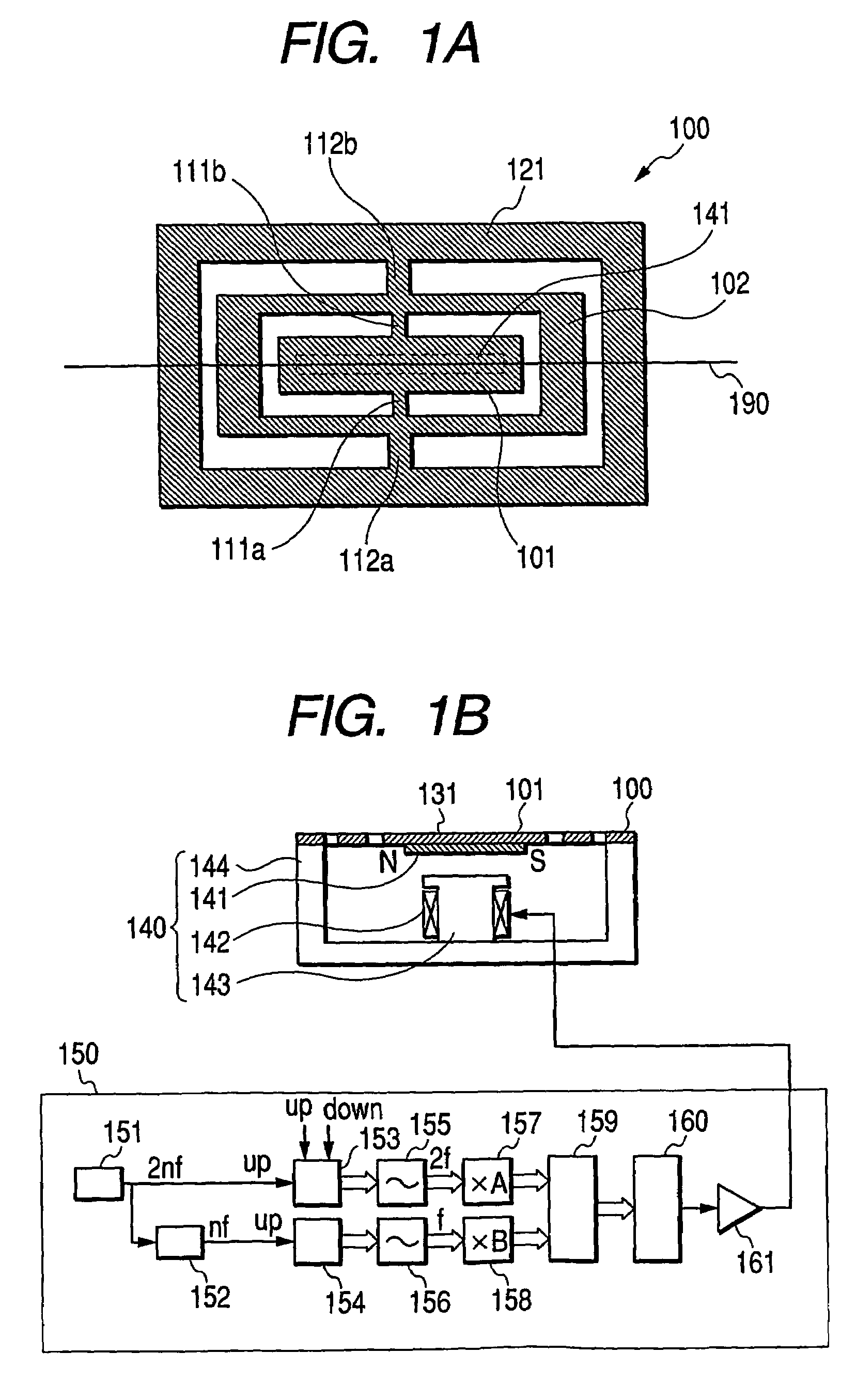
[0074]FIGS. 1A and 1B are views for explaining a light-deflector of the present embodiment. The light-deflector of the present embodiment consists of the micro-oscillating member and a light-reflecting film 131 formed on the upper surface of a movable element 101. And the micro-oscillating member consists of a plate member 100, a electromagnetic actuator 140 and a controller 150.

[0075]FIG. 1A is a top view of a plate member 100 formed by etching-forming a silicon wafer. A flat movable element 101 is supported up and down in FIG. 1A by two pieces of torsion springs 111a and 111b. A frame-shaped movable element 102 supports the torsion springs 111a and 111b in its interior side, and is supported above and below in FIG. 1A by two pieces of torsion springs 112a and 112b. A frame-shaped support frame 121 supports the torsion springs 112a and 112b in its interior side. While the movable elements 101 and 102 and the torsion springs 111 and 112 have two oscillation modes, their frequencies ...

second embodiment

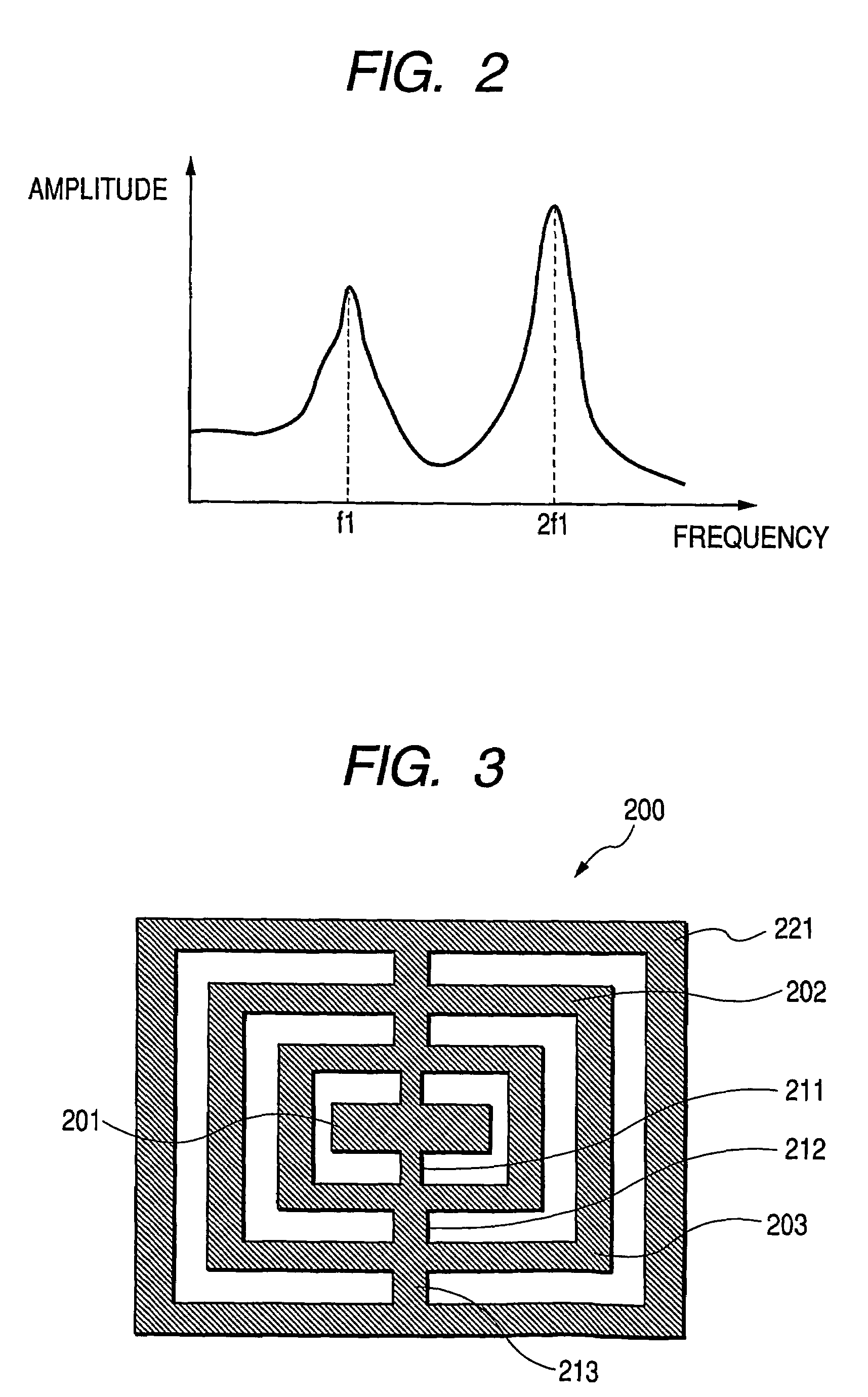
[0081]FIG. 3 is a top view of a plate member 200 formed by etching-working a silicon wafer. Flat movable elements 201 to 203 and torsion springs 211 to 213 are alternately connected in series. The axes of the torsion springs 211 to 213 are linearly arranged, and the other end of the torsion spring 213 is connected to a fixing frame 221. While this system has three oscillation modes, the frequencies thereof are adjusted so as to be in relation of approximately 1:2:3. These modes are hereinafter referred to as “mode 1”, “mode 2” and “mode 3”.

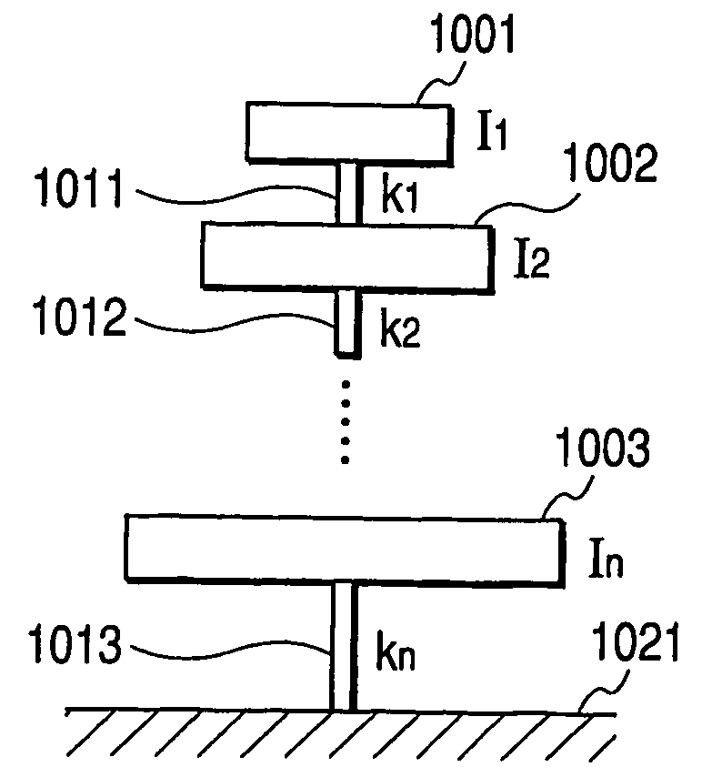
[0082]As an example, when the moments of inertia of the movable elements 201 to 203 and the torsion spring constants of the torsion springs 211 to 213 are I1, I2, I3, k1, k2, and k3, where I1=2.0E−11 [kgm2], I2=2.0E−10 [kgm2], I3=5.0E−10 [kgm2], k1=6.17854E−3 [Nm / rad], k2=2.03388E−2 [Nm / rad], and k3=3.52534E−2 [Nm / rad],

[0083]M-1⁢K=(3.08927×10⁸-3.08927×1080-3.08927×1071.32587×108-1.01694×1080-4.06776×1071.11284×108)

is established, and therefore, it...

third embodiment

[0086]FIG. 6 is an example in which the light-deflector of the present invention is applied to the image-forming apparatus such as the laser beam printer. A laser light 311 emitted from a light source 302 is shaped by an emission optical system 303, and is scanned by a light-deflector 301 of the present invention. An image-forming optical system 304 focuses the scanned laser light on a photosensitive drum 305 so as to form a spot. The scanned spot moves along a scanning trajectory 312.

[0087]In the image-forming apparatus of the present embodiment, the drawing of an image is performed in the range of an effective time t1eff shown by 1221 in FIG. 12. As evident from FIG. 11, in the light-deflector of the present invention, a scanning angular velocity fluctuates between θ′min (1212 in FIG. 11) and θ′max (1211 in FIG. 11) during the scanning.

[0088]When an ordinary fθ lens is used for the image-forming optical system 304, the scanning velocity on the photosensitive drum 305 fluctuates. B...


PUM


Abstract

The present invention provides a resonance type micro-oscillating member capable of retraining a fluctuation of angular velocity, and specifically provides a micro-oscillating member, which is a nested micro-oscillating member, wherein there exist a reference oscillation mode which is the characteristic oscillation mode of a reference frequency, and an even numbered oscillation mode which is the characteristic oscillation mode of a frequency being approximate even number times the reference frequency.

Description

TECHNICAL FIELD[0001]The present invention relates to a micro-oscillating member belonging to the technical field of a microstructure, and specifically to a micro-oscillating member suitable for a light-deflector, and a light-deflector using the micro-oscillating member. Further, the present invention relates to an image-forming apparatus, such as a scanning type display, a laser beam printer, or a digital copying machine, using this light-deflector.BACKGROUND ART[0002]Heretofore, various light-deflectors in which mirrors are resonance-driven have been proposed. In general, a resonance type light-deflector is characterized in that, comparing to a light scanning optical system using a polygonal rotating mirror such as a polygon mirror, the light-deflector can be made compact to an large extent, and the consumption power thereof can be reduced, and there exists no face tangle in theory, and particularly, a light-deflector comprising Si single-crystal manufactured by a semiconductor pr...

Claims


Application Information

Patent Timeline
Patent Type & Authority Patents(United States)
IPC IPC(8): G02B26/08B81B3/00G02B26/10
CPCG02B26/085G02B26/105Y10S359/904G02B26/08G02B26/10B81B3/00
Inventor YASUDA, SUSUMUSHIMADA, YASUHIRO
Owner CANON KK
Learn More