Passive optical network

a technology of optical network and optical fiber, applied in the field of fiber optic network, can solve the problems of inefficient approach in terms of information handling capacity and complexity

Inactive Publication Date: 2007-09-18
NORTHPEAK ENTERPRISES
View PDF40 Cites 69 Cited by
  • Summary
  • Abstract
  • Description
  • Claims
  • Application Information

AI Technical Summary

Benefits of technology

[0011]The fault tolerant ring-based passive optical network in accordance with the present invention satisfies the need for a short-haul, reliable, and fault-tolerant network, while overcoming deficiencies in previous networks.
[0012]The ring architecture used in the present invention provides for a passive optical network (PON) system with fault protection that prevents line failures due to cable cuts and wherein an Optical Network Unit (ONU) failure does not cause a service interruption. The ring architecture in addition minimizes the amount of optical fiber used, allows for a flexible geographic overlay, and allows both ends of the optical fiber to start and terminate within the Central Office (or other central facility) thereby simplifying system monitoring and fault location testing.
[0013]A Passive Optical Network (PON) is called “passive” because it eliminates “active” electronics in the network. Eliminating these active devices in the network increases the reliability of the network while reducing the amount of maintenance required. Typical fiber access architectures deliver data directly to large users on a switch service basis. This approach is inefficient in terms of the amount of information handling capacity provided and the complexity. The ring based PON of this invention provides a sensible cost-effective alternative which shares the enormous capacity of single mode fiber among groups of subscribers accessing a single fiber system. The network design is appropriate for a variety of passive all-optical networks, such as for subscriber loop access, and local and wide area networking.
[0015]The inventive network uses a common fiber cable that is connected at one end at the OLT, routes to ONUs in the field, and returns to the same OLT. Descriptions of single cables or single optic fibers, within the description include arrangements such as splices and connections wherein a single optic path is established. Several point-to-multipoint topologies are possible since a common fiber cable is employed which itself carries multiple bare fibers. The network can be organized to physically behave as a star or bus network, while being geographically deployed as a ring network with its numerous advantages.
[0020]In addition, a 4-fiber ring PON can be constructed which can operate with larger circumference rings. Each ONU employs redundant transmitters, wherein each is transmitting on a separate individual fiber within a single fiber cable. The OLT similarly transmits to individual fibers on the identical optical cable. Optical insertion loss is minimized by using only a single optical tap per fiber for each ONU, which maximizes the optical power budget of the network. Monitoring and fiber test ports can be added to the OLT.
[0023]Another object of the invention is to provide an optical network wherein the ONUs are connected passively to the network, such that failures within an ONU do not affect the remainder of the network.

Problems solved by technology

This approach is inefficient in terms of the amount of information handling capacity provided and the complexity.

Method used


Image

  • Passive optical network
  • Passive optical network
  • Passive optical network

Examples


Embodiment Construction

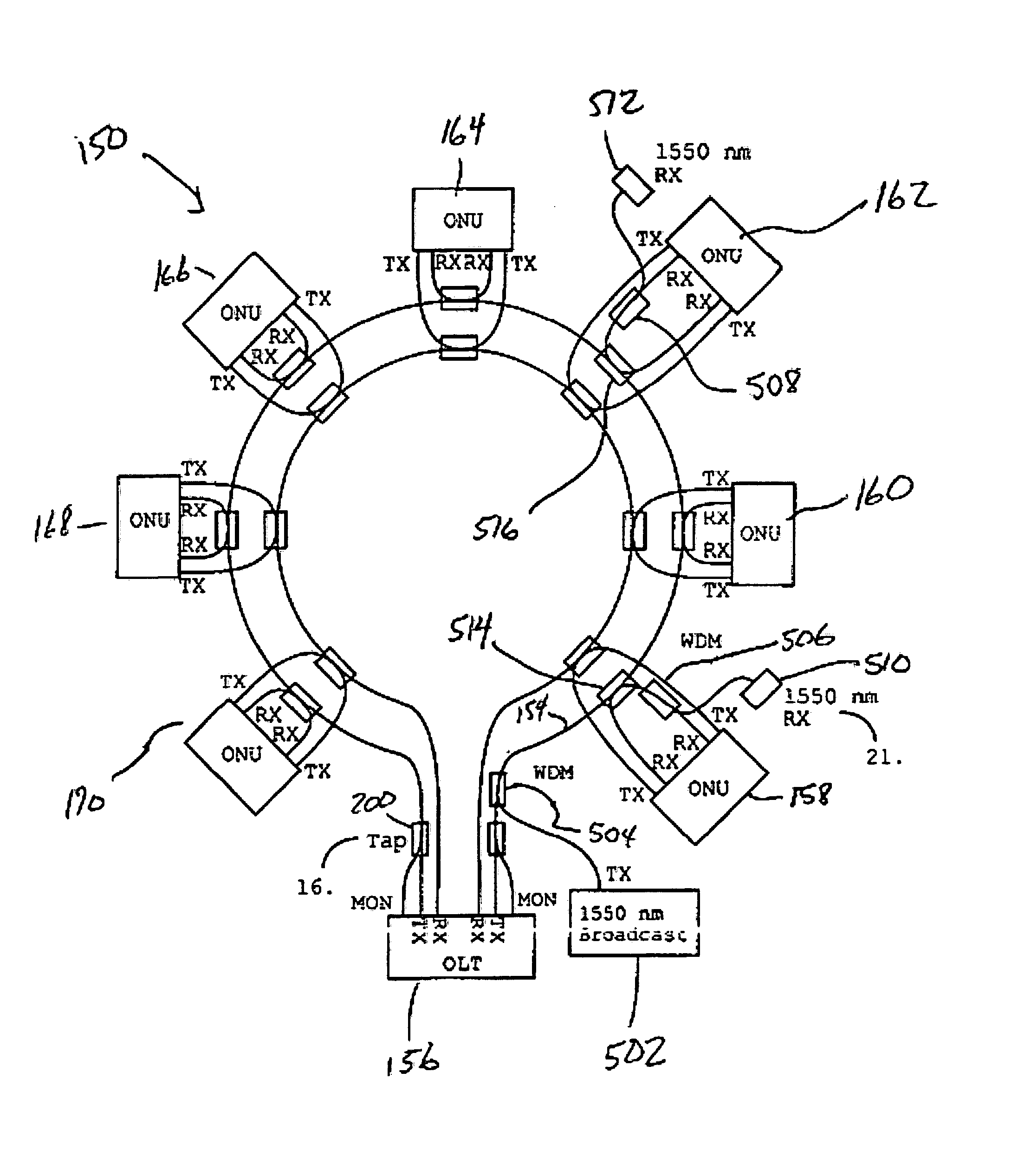
[0045]A passive optical network according to one embodiment of the present invention is shown in FIG. 5 and is indicated generally by reference character 150. As shown in FIG. 5, the PON 150 employs a fiber ring 151 consisting of a downstream optical fiber 152 and an upstream optical fiber 154 so as to provide the PON 150 with built-in redundancy and monitoring, as will be explained. The PON also includes an optical line terminal (“OLT”) 156 at which opposite ends 153, 155 of the fiber ring 151 terminate. The OLT 156 preferably distributes high bandwidth information to multiple optical network units (“ONUs”) 158-170. Each ONU may deliver any configured combination of voice, data, and video service and may receive / transmit a portion of the total bandwidth within the network. The OLT 156 is preferably installed in a central office, hub, or point-of-presence and provides interfaces (not shown) to digital switches and routers utilizing, for example, E1 / T1, E3 / T3, OC-3, OC-N, Ethernet, A...


PUM


Abstract

A passive optical network. The optical network has an optical fiber ring with ends terminating at an optical line terminal. The optical line terminal transmits signals through the fiber ring to optical network units passively connected to the fiber ring. The optical network units receive signals from the optical line terminal through the fiber ring. In one embodiment, the optical line terminal transmits redundant signals in opposite directions through the fiber ring and the optical network units receive the redundant signals from opposite directions through the fiber ring. In another embodiment, the optical network units receive TDM signals from and transmit TDMA signals to the optical line terminal through a fiber line. A first WDM coupler passively connected to the fiber line multiplexes an overlay signal with at least one of the TDM signals and the TDMA signals for transmission through the fiber line. The overlay signal has a wavelength different than the signals with which it is multiplexed.

Description

CROSS REFERENCE TO RELATED APPLICATIONS[0001]This application is a continuation-in-part of U.S. application Ser. No. 09 / 363,318 filed Jul. 28, 1999, which claims the benefit of U.S. Provisional Application No. 60 / 133,517 filed May 10, 1999. This application also claims the benefit of U.S. Provisional Application Nos. 60 / 133,514, 60 / 133,516, 60 / 133,517, 60 / 133,518, and 60 / 133,519 all filed May 10, 1999. The entire disclosures of the aforementioned applications are incorporated herein by reference.FIELD OF THE INVENTION[0002]The present invention relates generally to fiber optic networks and more particularly to passive optical networks employing a ring architecture for fault protection and passive optical networks employing a wavelength division multiplexing overlay for increased bandwidth.BACKGROUND OF THE INVENTION[0003]A passive-optical network (“PON”) is a fiber optic network to which users are connected through passive rather than active devices. PONs are commonly used to provid...

Claims


Application Information

Patent Timeline
Patent Type & Authority Patents(United States)
IPC IPC(8): H04J14/08
CPCH04J14/02H04J14/0227H04J14/0283H04J14/0294H04J14/0297H04J14/0241H04J14/0228
Inventor KUO, JER-CHENPESAVENTO, GERALD A.
Owner NORTHPEAK ENTERPRISES
Why Eureka
Try Eureka