
Vehicle stability enhancement system

a technology of stability enhancement and control system, which is applied in the direction of brake system, process and machine control, instruments, etc., can solve the problems of sensor bias always, high cost of side-slip velocity sensors, and the driver typically feels a loss of control of the vehicl

Inactive Publication Date: 2007-09-25
GM GLOBAL TECH OPERATIONS LLC
View PDF27 Cites 15 Cited by
  • Summary
  • Abstract
  • Description
  • Claims
  • Application Information

AI Technical Summary

Problems solved by technology

When an actual yaw rate and / or side-slip velocity of the vehicle significantly surpasses a desired value, a driver typically feels a loss of control of the vehicle.
However, side-slip velocity sensors are very expensive.
However, sensor bias always exists in sensors such as yaw rate sensors and lateral accelerometers.
Therefore, the integration drifts because the unwanted bias signal is also integrated.
Therefore, the estimation is not accurate.
However, GPS sensors are very expensive.

Method used


Image

  • Vehicle stability enhancement system
  • Vehicle stability enhancement system
  • Vehicle stability enhancement system

Examples


Embodiment Construction

[0025]The following description of the preferred embodiment(s) is merely exemplary in nature and is in no way intended to limit the invention, its application, or uses. For purposes of clarity, the same reference numbers will be used in the drawings to identify similar elements. As used herein, the term module refers to an application specific integrated circuit (ASIC), an electronic circuit, a processor (shared, dedicated, or group) and memory that execute one or more software or firmware programs, a combinational logic circuit, or other suitable components that provide the described functionality.

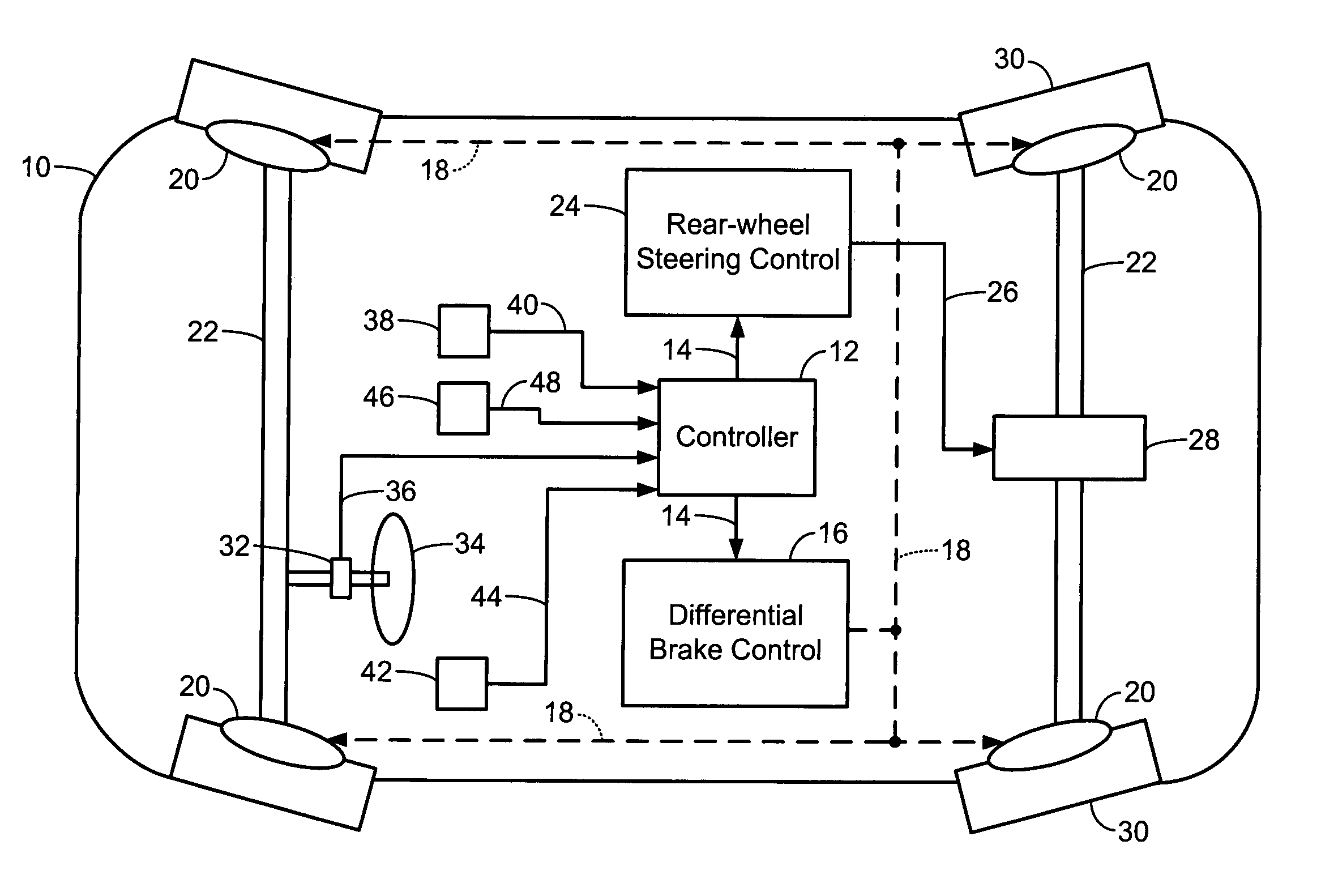
[0026]Referring to FIG. 1, a vehicle 10 includes rear-wheel steering and differential braking as part of a vehicle stability enhancement control system. To implement differential braking, a controller 12 sends an actuator control signal 14 to a differential brake control module 16. The differential brake control module 16 sends a brake control signal 18 to one or more brake actuators 20. ...


PUM


Abstract

A side-slip velocity estimation module for a vehicle stability enhancement control system includes a side-slip acceleration estimation module that estimates a side-slip acceleration of a vehicle. A multiple-order integrator integrates the side-slip acceleration to generate an estimated side-slip velocity of the vehicle. A reset logic module clears an output of the multiple-order integrator when the vehicle experiences a straight-driving condition, when a speed of the vehicle is less than a predetermined speed, and / or when a sensor bias condition occurs. The multiple-order integrator includes at least two accumulators and at least two feedback loops. The estimated side-slip velocity is a weighted sum of outputs of at least one of the at least two accumulators. A sum of the at least two feedback loops offsets the estimated side-slip acceleration.

Description

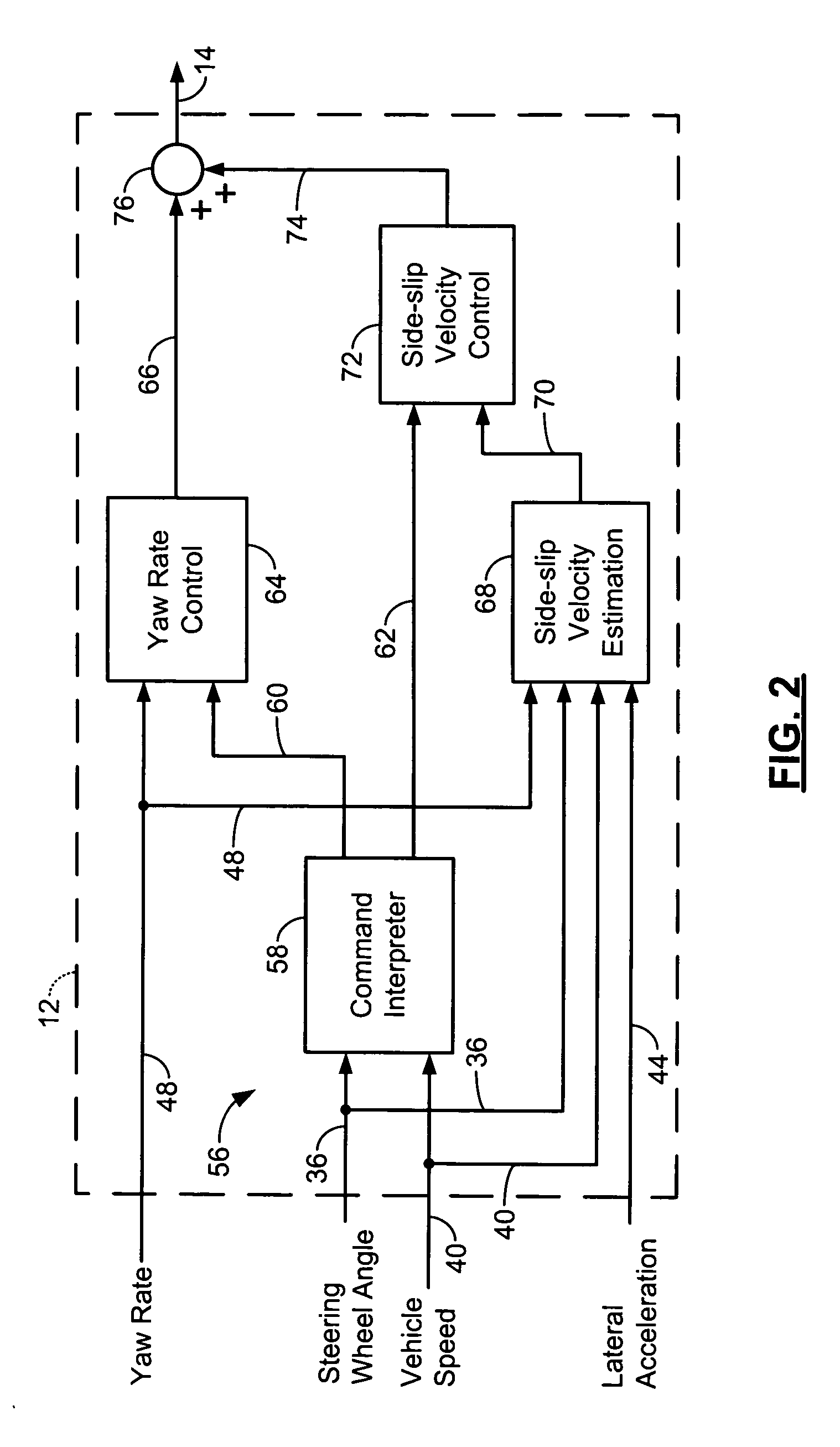
FIELD OF THE INVENTION[0001]The present invention relates to vehicle control systems, and more particularly to vehicle stability enhancement control systems.BACKGROUND OF THE INVENTION[0002]There are two motions that take place when a vehicle turns. A first motion is a turning motion called yaw motion. Yaw motion takes place as the vehicle spins around an imaginary axis that is vertical to the ground. A second motion is a lateral sliding motion called side-slip motion. Depending on a speed of the vehicle, side-slip motion occurs in the same direction as a turn or in an opposite direction of the turn.[0003]A command interpreter in a stability control system of a vehicle determines a desired yaw rate and a desired side-slip velocity for the vehicle based on speed and a position of a steering wheel. The desired yaw rate and side-slip velocity correspond with values that typically exist when a vehicle is traveling on a dry and clean surface. When an actual yaw rate and / or side-slip velo...

Claims


Application Information

Patent Timeline
Patent Type & Authority Patents(United States)
IPC IPC(8): G06F19/00B60T8/1755B62D7/15
CPCB60T8/17551B62D7/159B60T2230/02Y10T477/675Y10T477/60B60T2260/022
Inventor SHIN, KWANG-KEUNCHEN, SHIH-KENLIN, WILLIAM C
Owner GM GLOBAL TECH OPERATIONS LLC
Learn More