Disk brake pad

a technology of brake pads and discs, applied in the direction of brake elements, braking members, brake types, etc., can solve the problems of increasing the surface contact pressure of these end portions, increasing the noise reduction effectiveness reducing the noise reduction effect of the chamfered portion jb>10/b>, so as to inhibit uneven pad wear and promote long pad life.

Inactive Publication Date: 2007-10-02
ADVICS CO LTD
View PDF8 Cites 33 Cited by
  • Summary
  • Abstract
  • Description
  • Claims
  • Application Information

AI Technical Summary

Benefits of technology

[0037]It is an object of the present invention to provide a disk brake pad that controls rotation of a disk rotor by pushing a friction surface against the disk rotor while it is rotating. This disk brake pad helps to promote long pad-life and inhibits uneven pad-wear from occurring in a disk rotor rotation center direction.

Problems solved by technology

If the respective end portions of the disk brake pad 900 at the incoming and outgoing disk-rotor-rotation sides come into contract with the disk rotor, the surface contact pressure of these end portions is increased, whereby brake noise also increases.
Thus, the noise reduction effectiveness of the chamfered portion J10 is gradually diminished, whereby brake noise reduction performance worsens.
Further, if wear of the disk brake pad 900 in the disk rotor rotation center direction Y2 (namely, the central axis K of the friction surface 10) is uneven, then brake noise reduction performance deteriorates even more.
As a result, uneven wear of the disk brake pad 900 occurs, which causes the thickness of the disk brake pad 900 to become uneven.
In this way, uneven wear results from the work difference of the external and inner periphery portions of the disk rotor.
In addition, another cause of uneven wear is variation in pad surface contact pressure per unit area of the inside of the friction surface 10, which is caused by cylinder deformation that results from application of high hydraulic pressure.
Thus, when brake hydraulic pressure is low, the behavior of the disk brake pads 900 becomes unstable, which leads to the generation of brake noise.
This reduction in surface area leads the life of the disk brake pad 900 to become shorter due to an increase in wear thereof.

Method used


Image

  • Disk brake pad
  • Disk brake pad
  • Disk brake pad

Examples


first embodiment

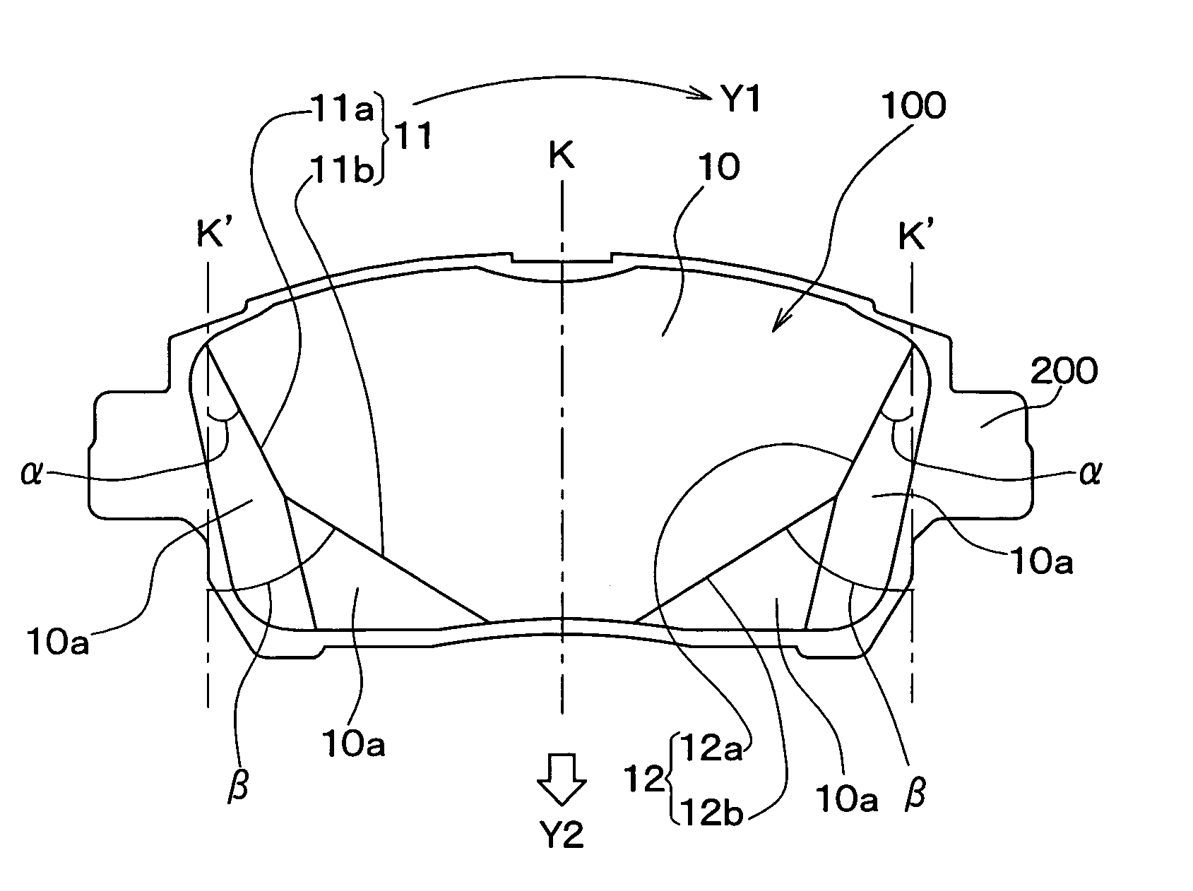
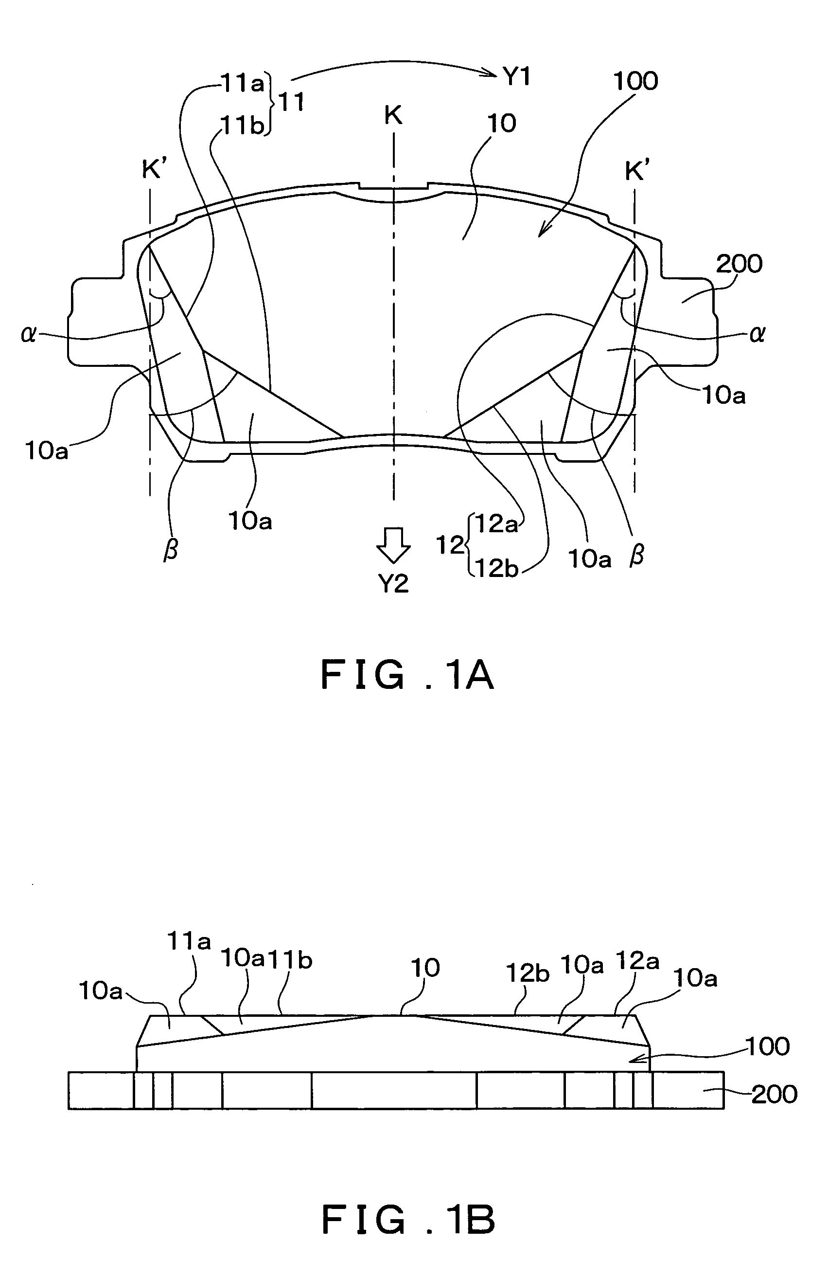
[0085]FIGS. 1A and 1B show the configuration of a disk brake pad 100 according to a first embodiment of the present invention. FIG. 1A shows a schematic plan view of the disk brake pad 100 as viewed from a front side of a friction surface 10 thereof, and FIG. 1B shows a side view of the disk brake pad 100 as viewed from the bottom of FIG. 1A.

[0086]The disk brake pad 100 according to the present invention controls rotation of a disk rotor 300 by using a cylinder 500 and a piston 400 to push the friction surface 10 against the disk rotor 300 while it rotates, in the same manner as described previously for FIG. 11.

[0087]As can be seen from FIG. 1, the disk brake pad 100 is integrally formed with a back plate (back metal) 200. Note that, the disk brake pad 100 is fixed to the back plate 200 at a back surface that is on the opposite side of the disk brake pad 100 to the friction surface 10.

[0088]Further, in a similar manner to above described FIG. 9A, the arrow Y1 indicates a rotation di...

second embodiment

[0143]The second embodiment of the present invention is a modified form of the above described first embodiment. Accordingly, the following description will mainly focus on points of difference between the two embodiments.

[0144]FIGS. 5A and 5B show the configuration of a disk brake pad 100′ according to the second embodiment. FIG. 5A shows a schematic plan view of the disk brake pad 100′ when viewed from a front of the friction surface 10, and FIG. 5B shows a side view of the disk brake pad 100′ as viewed from the bottom of FIG. 2A.

[0145]The friction surface 10 of the disk brake pad 100′ is formed with a fan-shape. With this disk brake pad 100′, an external periphery portion of the fan-shaped friction surface 10 directly forms the portion of the friction surface 10 that is farther from the disk rotor rotation center. Further, an inner periphery portion of the fan-shaped friction surface 10 directly forms the portion of the friction surface 10 that is closer to the disk rotor rotatio...


PUM


Abstract

A disk brake pad controls rotation of a disk rotor by pushing a friction surface against the disk rotor while it is rotating. The disk brake pad is formed with respective chamfered portions at respective end portions of the disk brake pad at the incoming and outgoing disk-rotor-rotation sides thereof. An edge of an end portion of the friction surface of the disk brake pad at the incoming disk-rotor-rotation side, and an edge of an end portion at the outgoing disk-rotor-rotation side are formed in a stepped bending shape such that a length of the friction surface in a circumferential direction of the disk rotor becomes shorter in a center of rotation direction of the disk rotor.

Description

CROSS REFERENCE TO RELATED APPLICATION[0001]This application is based upon and claims the benefit of Japanese Patent Application No. 2003-280813 filed on Jul. 28, 2003, the content of which are incorporated herein by reference.FIELD OF THE INVENTION[0002]The present invention relates to a disk brake pad that controls rotation of a disk rotor by pushing a friction surface against the disk rotor while it is rotating.BACKGROUND OF THE INVENTION[0003]Generally, disk brake pads are formed by mixing a fiber material such as organic fiber, inorganic fiber, or metal fiber, with a powdered material such, as a friction control agent or filler, and a binding agent such as a binder resin like phenol resin; and then thermoforming the mixed material composition thereof.[0004]When this type of disk brake pad is used, a friction surface of the disk brake pad is pushed against a rotating disk rotor, whereby rotation of the disk rotor is controlled by friction action of the friction surface. Accordin...

Claims


Application Information

Patent Timeline
Patent Type & Authority Patents(United States)
IPC IPC(8): F16D65/04F16D65/092F16D69/00F16D69/04
CPCF16D69/04F16D2069/004
Inventor OI, NOBUYUKIISHII, KATSUAKITAKEO, YUICHI
Owner ADVICS CO LTD
Why Eureka
Try Eureka