White light-emitting device using fluorescent fiber

a light-emitting device and fluorescent fiber technology, applied in the direction of fibre light guides, lighting and heating apparatus, instruments, etc., can solve the problems of reducing and achieve the effect of enhancing the efficiency of utilizing light and suppressing the generation of optical coupling loss

Inactive Publication Date: 2007-10-02
SUMITA OPTICAL GLASS
View PDF5 Cites 14 Cited by
  • Summary
  • Abstract
  • Description
  • Claims
  • Application Information

AI Technical Summary

Benefits of technology

[0009]In the light of the foregoing, it is an object of the present invention to provide a white light-emitting device, using a fluorescent fiber, in which generation of an optical coupling loss can be suppressed, and thus an efficiency of utilizing a light can be enhanced.
[0013]According to the present invention, the generation of the optical coupling loss can be suppressed, and thus the efficiency of utilizing the light can be enhanced.

Problems solved by technology

As a result, there is encountered such a problem that an optical coupling loss is generated between the optical fiber and the wavelength-converting member, and thus an efficiency of utilizing the light is reduced.

Method used


Image

  • White light-emitting device using fluorescent fiber
  • White light-emitting device using fluorescent fiber
  • White light-emitting device using fluorescent fiber

Examples


first embodiment

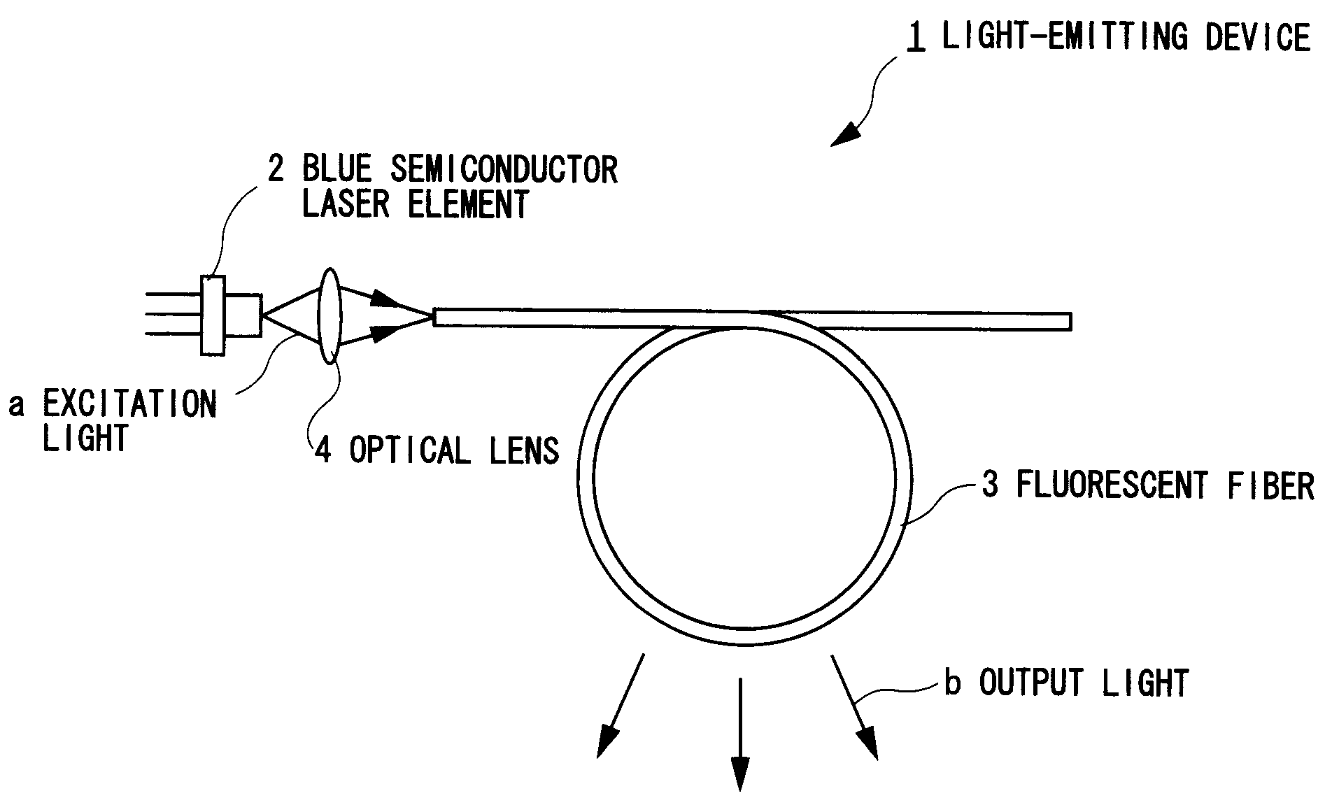
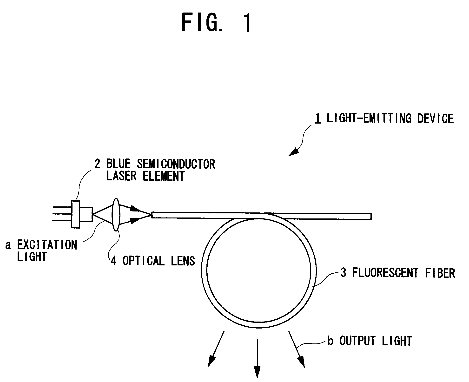
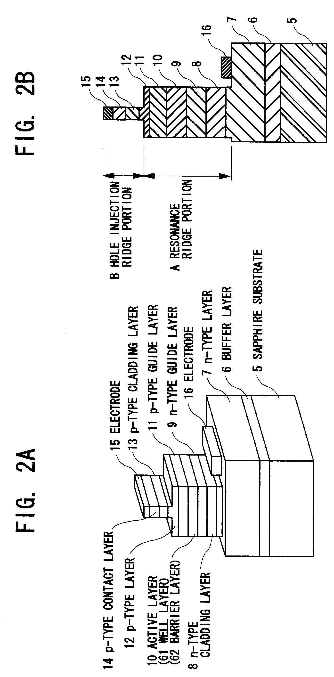
[0019]FIG. 1 is a plan view for explaining a white light-emitting device using a fluorescent fiber according to a first embodiment of the present invention, FIGS. 2A and 2B are respectively a perspective view and a cross sectional view for explaining a blue semiconductor laser element of the light-emitting device according to the first embodiment of the present invention, and FIG. 3 is a cross sectional view for explaining the fluorescent fiber of the white light-emitting device using a fluorescent fiber according to the first embodiment of the present invention.

[Overall Construction of Light-emitting Device 1]

[0020]Referring to FIG. 1, a light-emitting device 1 roughly includes a blue semiconductor laser element 2 as an excitation light source, a fluorescent fiber 3 through which optically multiplexed lights obtained by optically multiplexing an excitation light (blue light) “a” radiated from the blue semiconductor laser element 2, and wavelength conversion lights obtained through ...

second embodiment

[0038]FIG. 5 is a cross sectional view for explaining a fluorescent fiber of a light-emitting device according to a second embodiment of the present invention.

[0039]As shown in FIG. 5, the feature of the light-emitting device (as shown in FIG. 1) 1 shown in the second embodiment is that the light-emitting device 1 includes a fluorescent fiber 50 having a core 50A, a cladding member 50B including a first cladding member 50B-1 which is formed adjacently to the peripheral surface of the core 50A, and a second cladding member 50B-2 which is formed adjacently to a peripheral surface of the first cladding member 50B-1, and a core member 50C.

[0040]For this reason, a refractive index n1 of the first cladding member 50B-1 is set to one (n1≈1.48) that is smaller than that n2 (n2≈1.50) of the core 50A, but is larger than that n3 (n3≈1.45) of the second cladding member 50B-2.

[0041]According to the second embodiment as has been described so far, in addition to the effects (1) to (3) of the first...


PUM

PropertyMeasurementUnit
wavelengthaaaaaaaaaa
thicknessaaaaaaaaaa

Abstract

A white light-emitting device using a fluorescent fiber includes a blue semiconductor light-emitting element (2) for emitting an excitation light (a), and an optical fiber (3) having one side end face and the other side end face, the excitation light (a) emitted from the blue semiconductor light-emitting element (2) being made incident to the one side end face to be guided to the other side end face. The optical fiber (3) includes a core containing therein a phosphor for emitting wavelength conversion lights by being excited by the excitation light (a) received from the blue semiconductor light-emitting element (2), and a cladding member (3B) having a light emission surface in its peripheral surface, at least a part of optically multiplexed lights, which are obtained by optically multiplexing the wavelength conversion lights and the excitation light, being emitted through the light emission surface.

Description

CROSS-REFERENCE TO RELATED APPLICATIONS[0001]The present application is based on Japanese patent application No. 2005-346840, the entire contents of which are incorporated herein by reference.BACKGROUND OF THE INVENTION[0002]1. Field of the Invention[0003]The present invention relates to a white light-emitting device using a fluorescent fiber, and more particularly to a white light-emitting device, using a fluorescent fiber, which is suitable for being used as various kinds of a light source for a backlight for a liquid crystal television, and a light source including a neon tube.[0004]2. Description of Related Art[0005]In recent years, a light-emitting device using a semiconductor light-emitting element such as a light-emitting diode (LED) element or a light amplification by stimulated emission of radiation (LASER) element has been widely utilized as various kinds of a light source because it is advantageous in miniaturization, an excellent power efficiency, and a long life as comp...

Claims


Application Information

Patent Timeline
Patent Type & Authority Patents(United States)
IPC IPC(8): G02B6/02G02B6/12F21S2/00F21V8/00F21Y101/02G02B6/00G02F1/13357G02F2/02
CPCG02B6/001G02F1/133602G02B6/03633
Inventor YAMAZAKI, MASAAKIISHII, OSAMUSAWANOBORI, NARUHITONAGAHAMA, SHINOBU
Owner SUMITA OPTICAL GLASS
Why Eureka
Try Eureka