Aircraft tire

Inactive Publication Date: 2007-10-09
MICHELIN RECH & TECH SA
View PDF6 Cites 5 Cited by
  • Summary
  • Abstract
  • Description
  • Claims
  • Application Information

AI Technical Summary

Benefits of technology

[0021]Thus patent WO 02 / 00456 has already described aircraft tires, the carcass reinforcement of which comprises two or three circumferential alignments of reinforcement elements of high elasticity modulus and means for anchoring said reinforcement elements, constituting the carcass reinforcement, within each bead. The anchoring means according to this document are formed by circumferentially oriented cords axially bordering the circumferential alignments of the reinforcement elements of the carcass reinforcement, said reinforcement elements of the carcass reinforcement and the circumferentially oriented cords being separated by a bonding rubber mix of very high elasticity modulus. The use of cords makes it possible to obtain satisfactory rigidity with a bulk of the bead which is reduced as much as possible; the compactness of the bead is of paramount importance for aircraft tires in reducing the consequences of heating of said beads.
[0058]If necessary, the crown reinforcement comprising a central zone and two lateral zones, the working block furthermore comprises at least two layers of reinforcement elements, oriented substantially circumferentially, arranged axially on either side of the median plane of the tire in the lateral zones of said crown. These layers make it possible to withstand the forces due to centrifugation at high speed. They are preferably arranged radially internally relative to the two layers of circumferentially oriented reinforcement elements of the working block. These two reinforcement layers have the advantage of increasing the wrapping of the lateral zones of the crown without increasing the thickness thereof.

Problems solved by technology

During takeoff, very high speeds, of the order of 350 km / hour or even 450 km / hour, are achieved, and hence heating conditions exist which are also very severe.

Method used


Image

  • Aircraft tire
  • Aircraft tire
  • Aircraft tire

Examples


Embodiment Construction

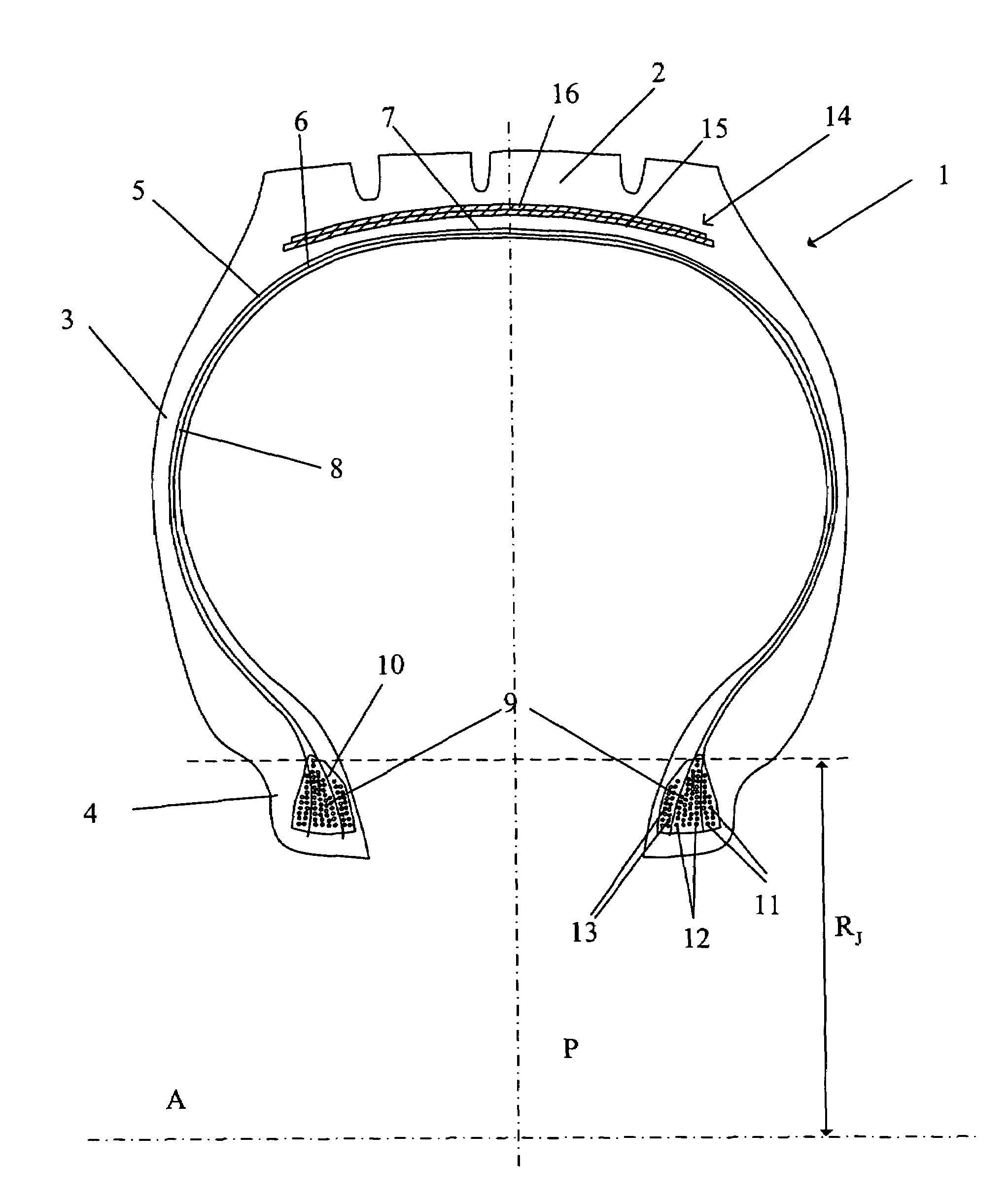
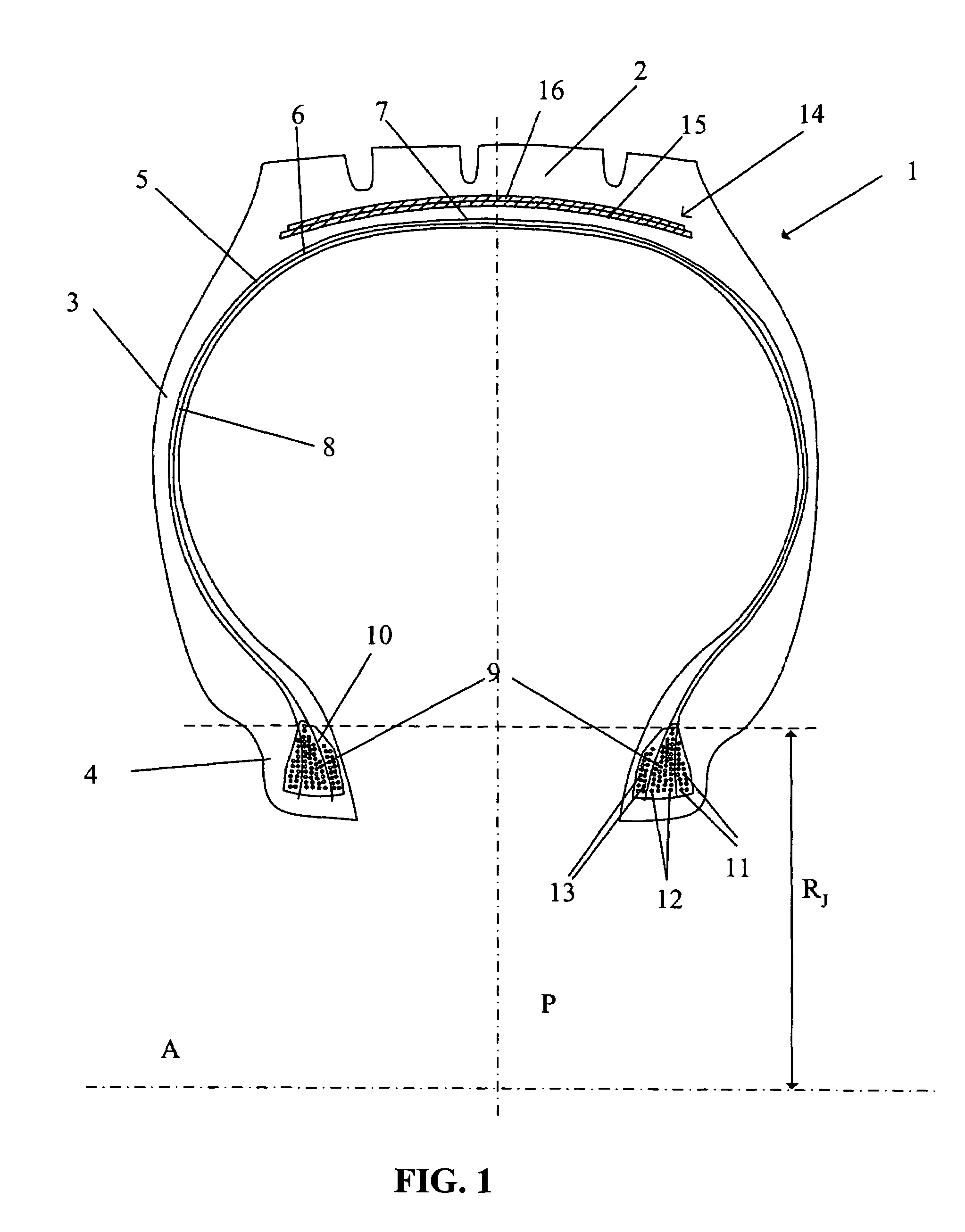
[0069]The aircraft tire 1 shown diagrammatically in axial half-section in FIG. 1 comprises a crown 2, two sidewalls 3 and two beads 4. A carcass reinforcement 5 extends from one bead 4 to the other and is formed of two circumferential alignments 6 and 7 of reinforcement elements. The circumferential alignments of the reinforcement elements 6 and 7 are oriented radially in the sidewalls 3 and are formed of reinforcement elements of aromatic polyamide or aramid. The reinforcement elements are arranged parallel to one another and are separated by a layer of mix 8 the nature and the modulus of which are adapted according to their position in the tire.

[0070]Anchoring of the two circumferential alignments 6 and 7 is provided in the beads 3 by alignments or “stacks”9 of circumferentially oriented wound cables arranged axially on either side of each circumferential alignment of the reinforcement elements 6 and 7. Each alignment or stack 9 of circumferentially oriented cables may be obtained...


PUM


Abstract

An aircraft tire has an inflation pressure greater than 9 bar and a deflection greater than 30%. The tire includes a crown, two sidewalls and two beads, a carcass reinforcement anchored in the two beads and a crown reinforcement. The carcass reinforcement includes at least one circumferential alignment of reinforcement elements and the mechanism for anchoring the reinforcement elements within each bead includes circumferentially oriented reinforcement elements axially bordering the circumferential alignments of said reinforcement elements of the carcass reinforcement. The reinforcement elements of the carcass reinforcement and the circumferentially oriented reinforcement elements are separated from each other by a bonding rubber mix of very high elasticity modulus. The circumferentially oriented reinforcement elements are in the form of cables having a penetrability of between 80 and 100%, the breaking load of the cables being greater than 150 daN, and the cables having an elongation at break greater than 4%.

Description

[0001]This application is a continuation of International Application Serial No. PCT / EP2003 / 014652 filed on Dec. 19, 2003, and which published on Jul. 8, 2004 under Document WO 2004 / 056589.BACKGROUND[0002]The invention relates to an aircraft tire. Aircraft tires are distinguished in particular by the combination of an inflation pressure greater than 9 bar and a relative deflection greater than 30%.[0003]The deflection of a tire is defined by the radial deformation of the tire, or variation in the radial height, when it changes from a non-loaded state to a statically loaded state, under rated load and pressure conditions.[0004]It is expressed in the form of a relative deflection, defined by the ratio of this variation in the radial height of the tire to half the difference between the external diameter of the tire and the maximum diameter of the rim measured on the hook. The external diameter of the tire is measured statically in a non-loaded state at the rated pressure.[0005]The rei...

Claims


Application Information

Patent Timeline
IPC IPC(8): B60C15/00B60C15/06B60C9/00B60C9/02B60C15/024B60C15/04B60C19/00
CPCB60C9/023B60C15/0018B60C15/024B60C15/04Y10T152/10819Y10T152/10855Y10T152/10846Y10T152/10864B60C2200/02
Inventor MONNERIE, CHRISTIAN
Owner MICHELIN RECH & TECH SA
Why Eureka
Try Eureka