
Electrospraying apparatus and method for coating particles

a technology of electro-spraying and coating particles, which is applied in the direction of spraying discharge apparatus, liquid spraying plant, granule coating, etc., can solve the problems of low transformation frequency, high cost, and high cost of coating particles,

Inactive Publication Date: 2007-10-09
RGT UNIV OF MINNESOTA
View PDF158 Cites 142 Cited by
  • Summary
  • Abstract
  • Description
  • Claims
  • Application Information

AI Technical Summary

Benefits of technology

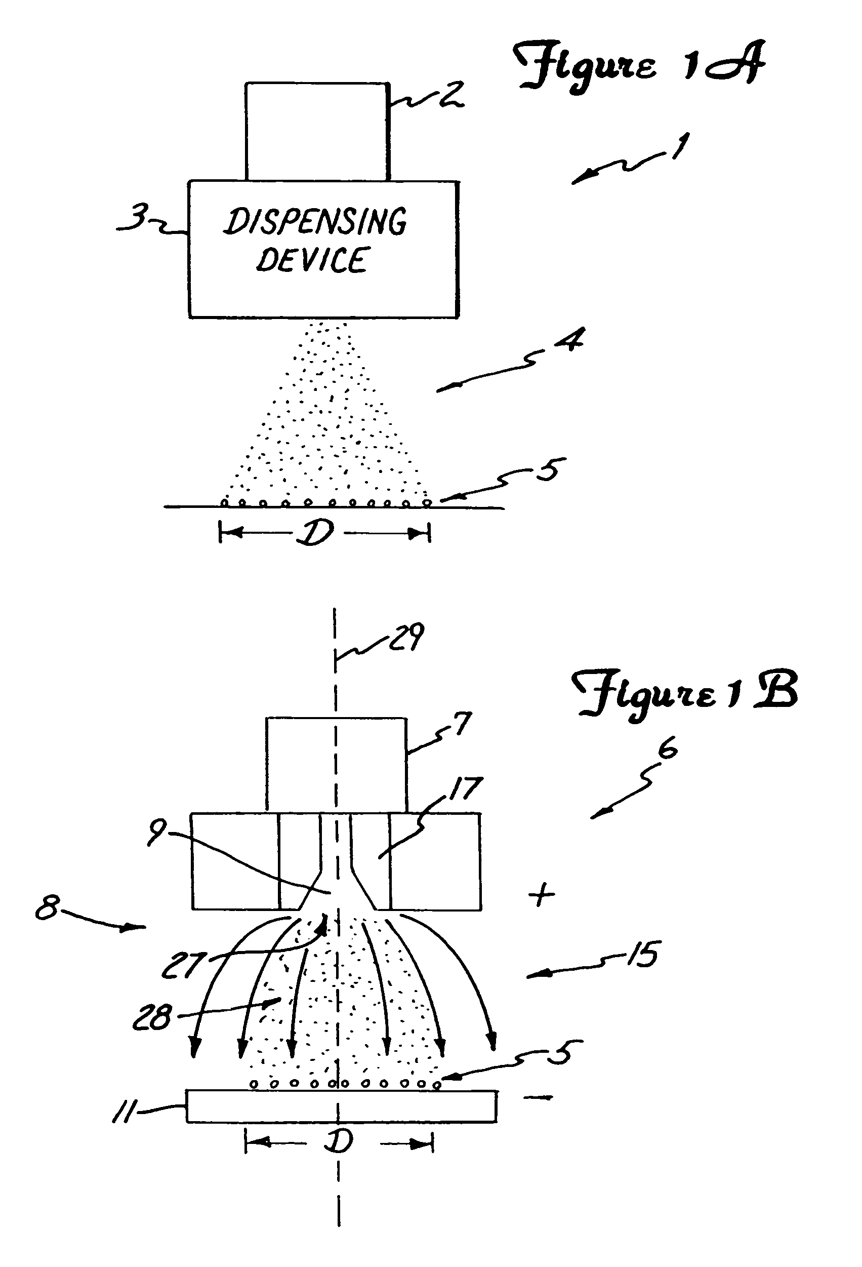
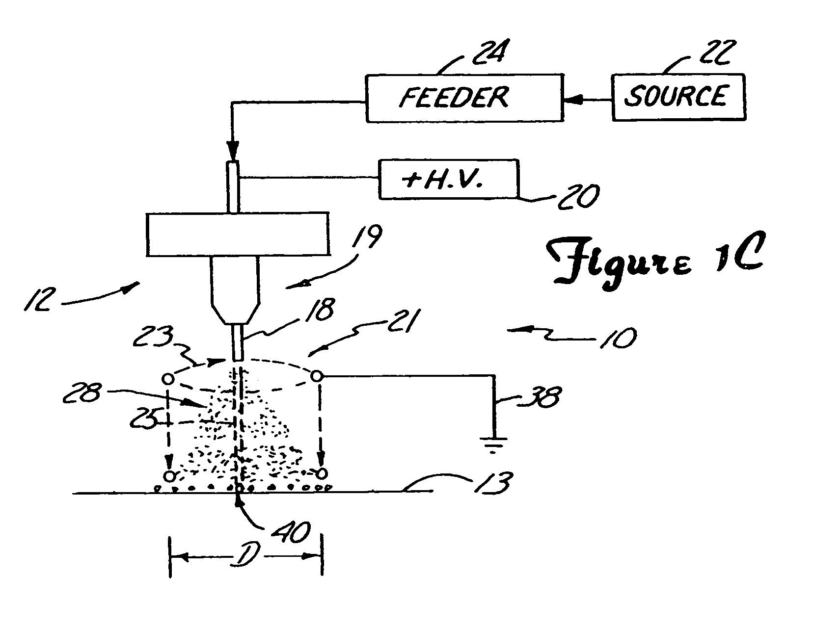
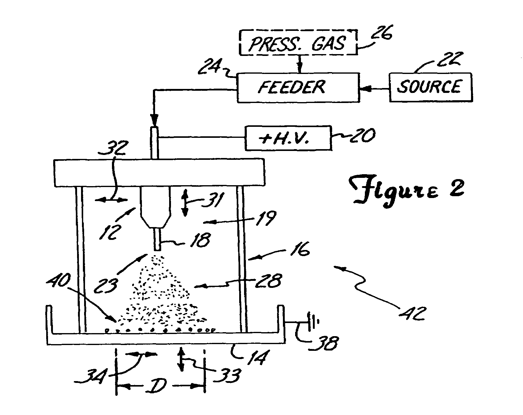
[0018]In another embodiment, the space charge effect of the concentrated electrical charge on the substantially dispersed particles of the spray enable one or more of the particles to be introduced into one or more of the target cells. The electrical charge concentrated on a particular particle is in the range of about 80 percent to about 95 percent of a maximum charge that can be held by the microdroplet suspending the particular particle.

Problems solved by technology

These uptake protocols generally are quite simple and allow for treatment of large numbers of cells at one time, but this technique tends to have a very low efficiency, i.e., transformation frequency is low.
Cell fusion technologies may have better efficiencies than uptake mechanisms, but cell selection can be more complex, and the resulting cells are typically of elevated ploidy, which makes them of limited use.
When very small cells are to be injected, very sharp capillary tubes are required, whose tips are very easily broken or clogged.
High pressures are required to cause bulk flow through the small orifices and regulation of such flow is difficult.
Although efficiency of microinjection, as one might expect is high, transformation of individual cells is by single cell manipulation and therefore treatment of masses of cells is difficult.
However, such mechanical shock techniques have various disadvantages.
Agglomeration of the particles may cause undesirable pit damages to the target cells upon impact therewith.
Yet further, preparation of coated or impregnated particles is a time consuming process.
In addition, the overall process is not easily controlled.
Further, for example, the delivery of particles uniformly to the target cells is not easily controlled.
As such, target cells located at certain positions may be damaged more easily than those target cells surrounding such positions.
For example, target cells located at the center of a batch of target cells may be damaged or killed more readily than those in the surrounding target-area when bombarded by coated or impregnated particles by conventional batch gene gun devices.
As the overall process is not easily controlled, the amount of biological material being delivered to the target cells is not readily controllable.
However, such techniques do not alleviate all of such problems.
For example, the aerosol technique may allow for a more continuous transfer method as opposed to a batch method, but still has the associated agglomeration disadvantages.

Method used


Image

  • Electrospraying apparatus and method for coating particles
  • Electrospraying apparatus and method for coating particles
  • Electrospraying apparatus and method for coating particles

Examples


example 1

[0115]Using an apparatus equivalent to that shown in and described with reference to FIG. 7 modified with the dual capillary tube distributor head 400 shown in and described with reference to FIG. 8, biological material transfer was successfully accomplished. The apparatus used was configured with a center capillary tube 413 having an outer diameter of about 229 μm to about 241 μm and an inner diameter of about 89 μm to about 127 μm. The second capillary tube 414 concentric with the center capillary tube had an outer diameter of about 533 μm to about 546 μm and an inner diameter of about 394 μm to about 432 μm. The distance d1 shown in FIG. 8 from the end of tapered section 335 to the end of the metal casing 322 is about 2 cm. The diameter d2 of the first end 336 of the nozzle portion or metal casing 322 is about 0.5 cm. The outer diameter d4 of the second end 338 of the nozzle portion 322 is about 1715 μm to about 1740 μm and an inner diameter d3 of about 1333 μm to about 1410 μm. ...

example 2

[0122]The same setup of Example 1 was used. The only difference was that Au particles were not added to the suspension and the voltage applied to the element 312 was 5600 volts such that the dispensing device was operated in cone jet mode. Again, the UV microscope was used to visually note the fluorescence. Approximately 40 percent to 60 percent of the cells fluoresced. As fluorescence was noted, introduction of biological material into the cell was successful.


PUM

PropertyMeasurementUnit
diameteraaaaaaaaaa
diameteraaaaaaaaaa
diameteraaaaaaaaaa

Abstract

An electrospraying apparatus and / or method is used to coat particles. For example, a flow including at least one liquid suspension may be provided through at least one opening at a spray dispenser end. The flow includes at least particles and a coating material. A spray of microdroplets suspending at least the particles is established forward of the spray dispenser end by creating a nonuniform electrical field between the spray dispenser end and an electrode electrically isolated therefrom. The particles are coated with at least a portion of the coating material as the microdroplet evaporates. For example, the suspension may include biological material particles.

Description

[0001]The present application is a divisional application of Ser. No. 10 / 162,031, filed on Jun. 3, 2002 now U.S. Pat. No. 6,746,869, entitled ELECTROSPRAYING APPARATUS AND METHOD FOR COATING PARTICLES, which is a continuation application of Ser. No. 09 / 577,747 filed on May 23, 2000, issued as U.S. Pat. No. 6,399,362, which is a divisional application of Ser. No. 09 / 092,794 filed on Jun. 5, 1998, issued as U.S. Pat. No. 6,093,557, which claims benefit of 60 / 049,444 filed on Jun. 12, 1997, all of which are incorporated by reference herein.BACKGROUND OF THE INVENTION[0002]Various devices and methods for use in genetic transformation of plant and animal cells have been utilized and many others have been described in various publications. For example, a few early techniques for accomplishing the transport of substances, e.g., DNA, into cells, include uptake mechanisms, fusion mechanisms, and microinjection mechanisms. Generally, uptake mechanisms include the use of substances, such as, f...

Claims


Application Information

Patent Timeline
Patent Type & Authority Patents(United States)
IPC IPC(8): C12N15/88A61K39/00A61K48/00B01J2/00B01J2/04B05B5/025B05B5/03B05B5/053B05B5/08C12M3/00C12N15/82C12N15/87C12N15/89
CPCC12N15/895B01J2/006B01J2/04B05B5/025B05B5/03B05B5/0533B05B5/081B05B5/082B05B5/084B05B5/087C12M35/02C12N15/8207C12N15/87A61K39/00B01J2219/00371B01J2219/00436B05B13/04A61K48/00
Inventor PUI, DAVID Y. H.CHEN, DA-REN
Owner RGT UNIV OF MINNESOTA
Learn More