Output regulating device for regulating output of electric power source depending on input therefrom

a technology of output control and output power, which is applied in the direction of dc-dc conversion, power conversion systems, instruments, etc., can solve the problems of insufficient output power to drive a load, insufficient protection provided by the protective circuit for protecting insufficient internal impedance to protect the electric power source, etc., to achieve stable operation, maintain a connected load, and high internal impedance

Inactive Publication Date: 2007-10-09
TAIYO YUDEN KK
View PDF12 Cites 39 Cited by
  • Summary
  • Abstract
  • Description
  • Claims
  • Application Information

AI Technical Summary

Benefits of technology

[0017]Accordingly, an object of the present invention is to provide an output control device for an electric power source for preventing the electric power source from malfunctioning due to a sharp drop in an input current from the electric power source having a relatively high internal impedance to protect the electric power source, and maintaining a connected load at a stable operation.
[0020]Preferably, an output current to a load is heightened by maintaining the lower limit value of the input voltage at the predetermined value in the lower limit value sustaining mode.
[0029]In accordance with preferred embodiments of the present invention, the input detector circuit detects the input voltage, the input current, and the input power from the electric power source, and the converter circuit for converting the input voltage from the electric power source to the output voltage has the lower limit value sustaining mode in which the lower limit value of the input voltage is maintained at the predetermined value in response to the detected output of the input detector circuit. This arrangement prevents the output voltage of the electric power source from dropping below a specified value of the electric power source, thereby avoiding damaging the electric power source. Since sufficient power to drive a load is picked up from the output of the electric power source, operational stability of the load is assured.
[0030]In accordance with the preferred embodiments of the present invention, the input detector circuit detects the variations in the input voltage, the input current, and the input power from the electric power source, and the converter circuit for converting the input voltage from the electric power source to the output voltage has the current increasing mode in which the output current is increased while the variation in the input detected by the input detector circuit is maintained within the constant range by varying the output voltage. This arrangement prevents the output voltage of the electric power source from dropping below a specified value of the electric power source, thereby avoiding damaging the electric power source. Since sufficient power to drive a load is picked up from the output of the electric power source, operational stability of the load is assured.

Problems solved by technology

These protective circuits protect the switching power supply circuit, or a circuit, electrical components, and devices connected thereto as a load, but does not protect the electric power source.
The output short protective circuit and the output excessive current protective circuit limit input power from the electric power source, namely, these protective circuits limit the input power to the switching supply circuit.
The level of protection provided by the protective circuit for protecting the electric power source is not satisfactory because the precision of the circuit for limiting power is poor, and because the protective circuit does not monitor directly an input voltage Vin and an input current Iin.
As a result, the output current falls resulting in the output power being insufficient to drive a load.
As a result, an input voltage Vin continuously decreases, and the output control device is unable to maintain the output voltage Vout at a desired value.
However, a high output current lout causes a high input current Iin, leading to a low input voltage Vin.
As a result, the input voltage Vin sharply drops, damaging the electric power source and leading to the output of insufficient power to a connected load.
Such a malfunction occurs in all power supply having an internal impedance.
The higher the internal impedance of the electric power source, the more pronounced the malfunction becomes.

Method used


Image

  • Output regulating device for regulating output of electric power source depending on input therefrom
  • Output regulating device for regulating output of electric power source depending on input therefrom
  • Output regulating device for regulating output of electric power source depending on input therefrom

Examples


first preferred embodiment

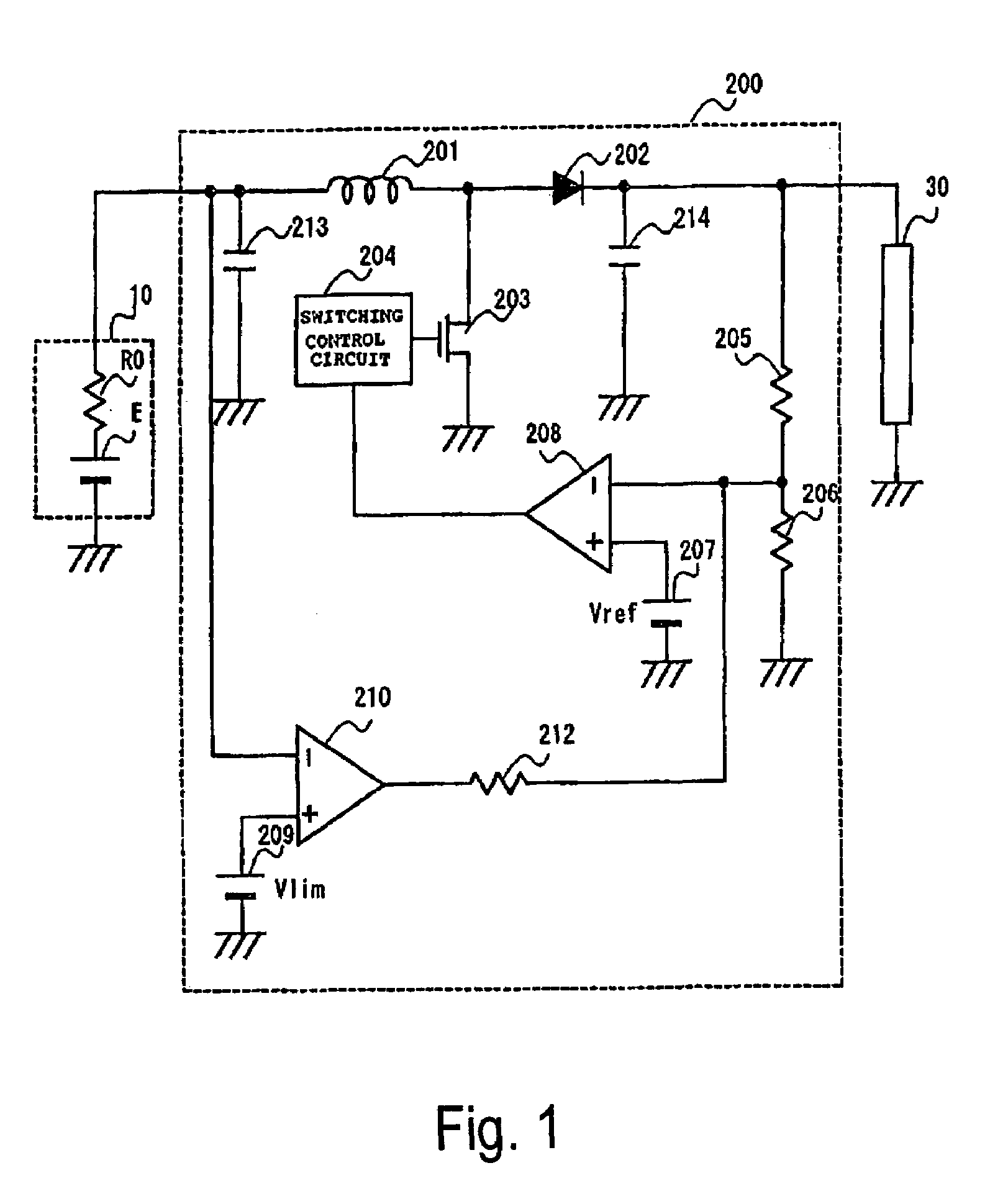
[0044]FIG. 1 is a circuit diagram of an output control device 200 of an electric power source in accordance with a first preferred embodiment of the present invention.

[0045]The output control device 200 supplies power from a fuel cell 10 as an electric power source to a load 30.

[0046]The fuel cell 10 includes a power source E having a large internal impedance R0.

[0047]The output control device 200 includes a coil 201 receiving the output of the fuel cell 10, a field-effect transistor 203 for switching the output of the coil 201, a diode 202, a pulse-width modulation (PWM) circuit 204 for switch controlling the field-effect transistor 203, resistors 205 and 206 for detecting an output voltage Vout of the output control device 200, a reference voltage generator 207 for generating a reference voltage Vref controlling the PWM circuit 204, a differential amplifier 208 for generating a control signal for controlling the PWM circuit 204, a lower limit value setter 209 for setting a lower l...

second preferred embodiment

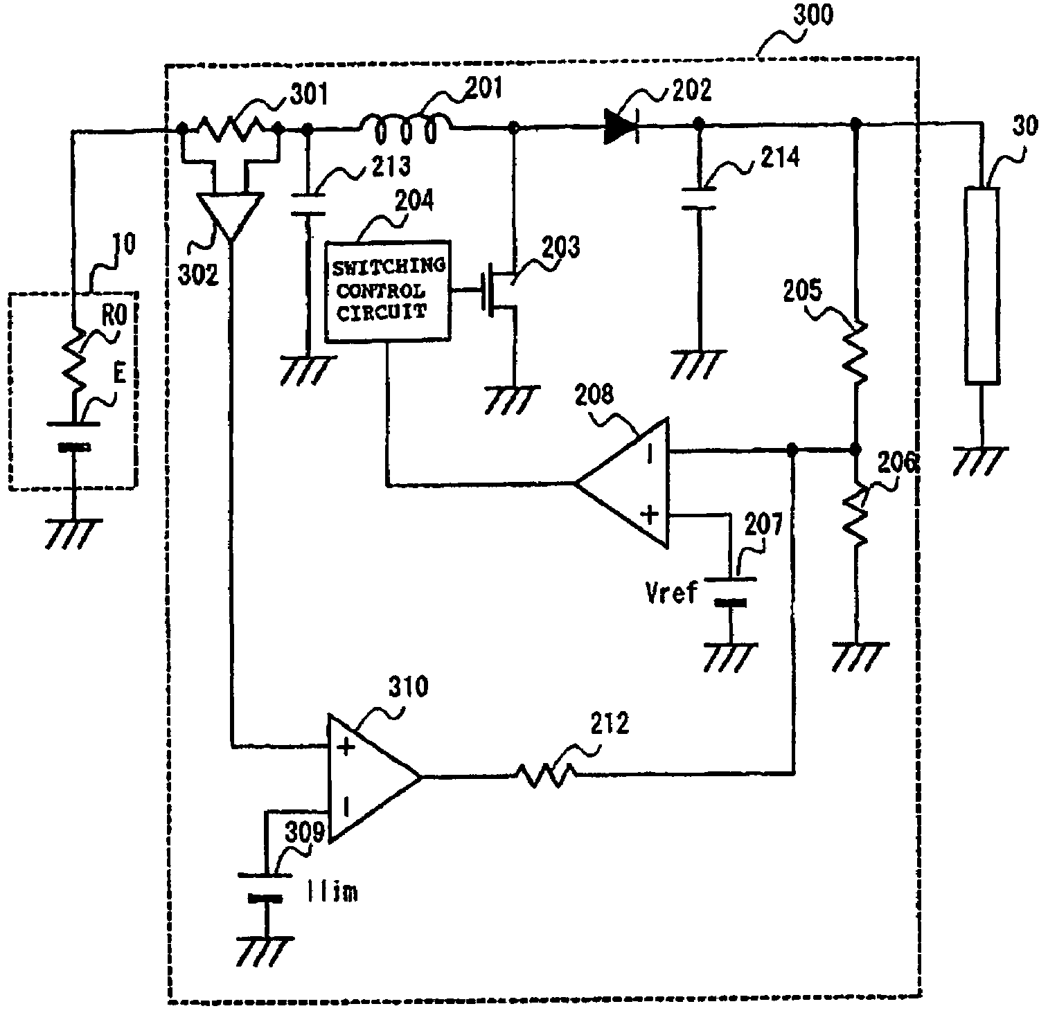
[0064]FIG. 4 is a circuit diagram of an output control device 300 of the electric power source in accordance with a second preferred embodiment of the present invention.

[0065]In accordance with the second preferred embodiment of FIG. 4, the output control device 300 supplies power to a load 30 from a fuel cell 10 as an electric power source. The output control device 300 includes a resistor 301 along an output line of the fuel cell 10. An amplifier 302 detects a voltage drop across the resistor 301, thereby detecting the output current of the fuel cell 10, namely, the input current Iin of the output control device 300.

[0066]The input current Iin, detected by the amplifier 302, is supplied to a positive input terminal of a comparator 310. The comparator 310 receives, at the negative input terminal thereof, an upper limit value Ilim of the input current Iin of the output control device 300 set by an upper limit value setter 309. The rest of the structure of the output control device 3...

third preferred embodiment

[0075]FIG. 5 is a circuit diagram of an output control device 400 of the electric power source in accordance with a third preferred embodiment of the present invention.

[0076]As shown in FIG. 5, the output control device 400 supplies the load 30 with power from the fuel cell 10 as an electric power source. The output control device 400 monitors a variation ΔV in the output voltage of the fuel cell 10, namely, the input voltage Vin of the output control device 400.

[0077]Referring to FIG. 5, a capacitor 213 is connected to the input line from the fuel cell 10 with one terminal and the other terminal thereof grounded. A capacitor 214 is connected to a diode 202 with one terminal thereof connected to the output line of the diode 202 and with the other terminal thereof grounded.

[0078]The input line from the fuel cell 10 is connected to the output line of the diode 202 through a capacitor 403, and resistors 405 and 404. A transistor 406 is configured with the base thereof connected to the ...


PUM

PropertyMeasurementUnit
input voltageaaaaaaaaaa
voltageaaaaaaaaaa
input currentaaaaaaaaaa

Abstract

If an input voltage to an output control device is above a lower limit value, the output control device operates in a constant voltage control mode for maintaining an output voltage at a substantially constant voltage. If the input voltage of the output control device falls below the lower limit value, the output voltage is controlled to be lower than the constant voltage in the constant voltage control mode, and the output control device operates in a lower limit value sustaining mode for maintaining the input voltage at the lower limit value. Then, the output control device shifts to a current increasing mode in which the output current rises as the output voltage falls.

Description

BACKGROUND OF THE INVENTION[0001]1. Field of the Invention[0002]The present invention relates to an output control device for an electric power source, having a converter circuit for converting an input voltage from the electric power source to an output voltage and, in particular, to an output control device for protecting an electric power source by preventing malfunction due to a sharp drop in the input voltage from the electric power source having a relatively large internal impedance.[0003]2. Description of the Related Art[0004]Output control device control an input from an electric power source such as a fuel cell with a switching power supply circuit thereof, thereby controlling an output to a load. Known output control device typically include an output short-circuit protective circuit, an output excessive current protective circuit, or an input excessive voltage protective circuit, etc.[0005]These protective circuits protect the switching power supply circuit, or a circuit,...

Claims


Application Information

Patent Timeline
Patent Type & Authority Patents(United States)
IPC IPC(8): G05F1/10G05F5/00H02M3/28H01M8/04H02M3/155H02M3/156
CPCH02M3/156Y02E60/50H01M8/04
Inventor OOTANI, MITSUAKIHOSAKA, YASUO
Owner TAIYO YUDEN KK
Why Eureka
Try Eureka