Method and apparatus for forming nano-particles

a nano-particle and nano-particle technology, applied in auxillary shaping apparatus, manufacturing tools, transportation and packaging, etc., can solve the problems of nano-particles produced by ball milling that are non-uniform in size and shape, wear of grinding media and mill, and contamination of final products, so as to reduce flow turbulence, improve particle size distribution, and reduce turbulence.

Active Publication Date: 2007-10-16
VIVAKOR INC +1
View PDF16 Cites 68 Cited by
  • Summary
  • Abstract
  • Description
  • Claims
  • Application Information

AI Technical Summary

Benefits of technology

[0009]An aspect of at least one of the inventions disclosed herein includes the realization that significant improvements in particle size distribution can be achieved by reducing turbulence in the flows of vaporized material and cooling gas. For example, in a thermal-type process for forming nano-scale particles, a reduction in the turbulence of the flow of vaporized material and / or cooling gas allows the vaporized particles to be quenched in a more uniform manner, thereby resulting in better (e.g., narrower) particle size distribution.

Problems solved by technology

There are several disadvantages to this approach.
The grinding media and the mill wear away and combine with the nanomaterial, contaminating the final product.
Additionally, nanoparticles produced by ball milling tend to be non-uniform in size and shape and have a wide distribution of particle sizes.
Such methods can produce powders contaminated by unreacted materials such as carbon.
Ion collision and electron beam evaporation tend to be too slow for commercial processes.
Laser ablation has the disadvantage of being extremely expensive due to an inherent energy inefficiency.
This process produces particles with a large size distribution, uses large quantities of gas, and is difficult to scale to commercial bulk production.

Method used


Image

  • Method and apparatus for forming nano-particles
  • Method and apparatus for forming nano-particles
  • Method and apparatus for forming nano-particles

Examples


Embodiment Construction

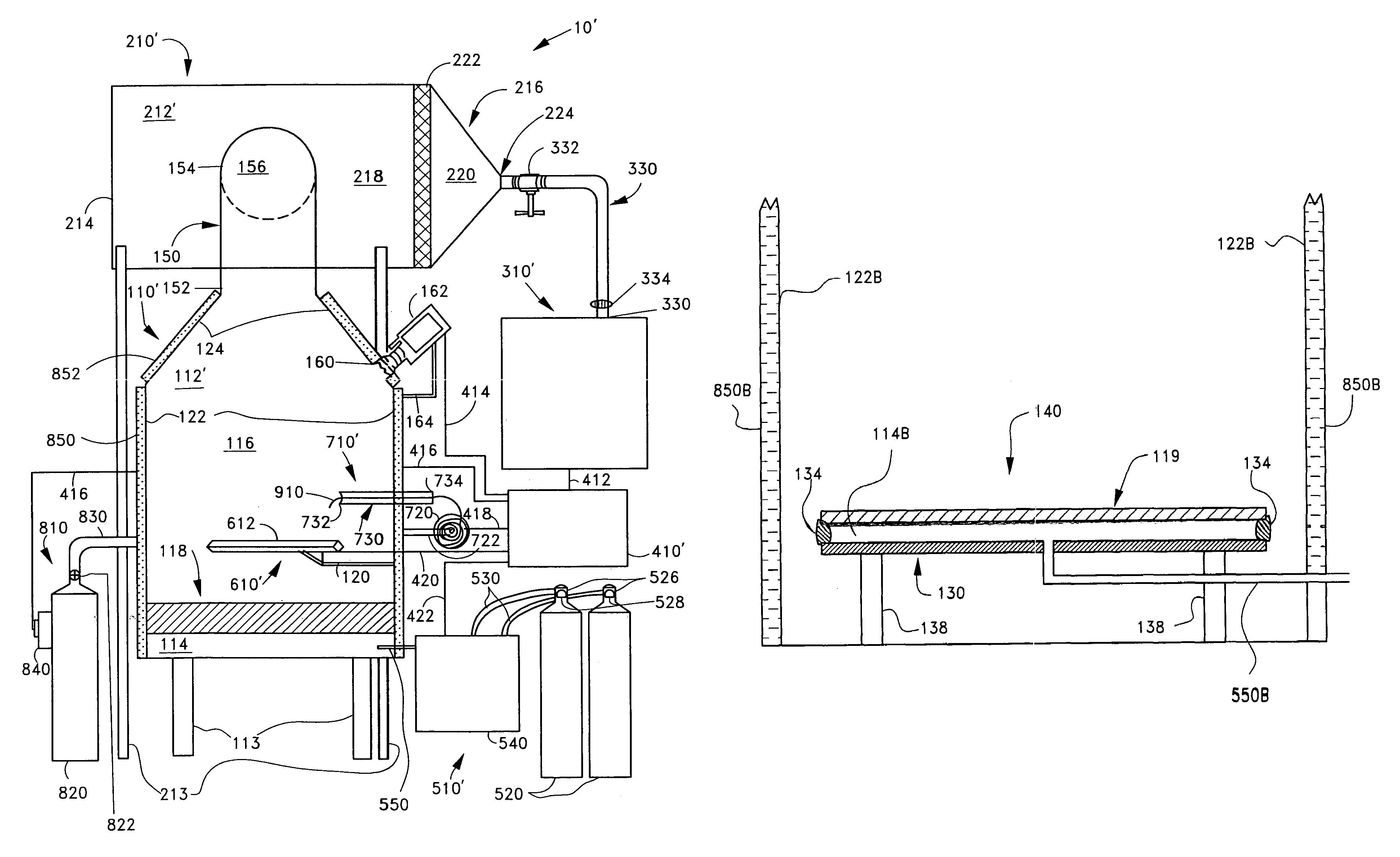
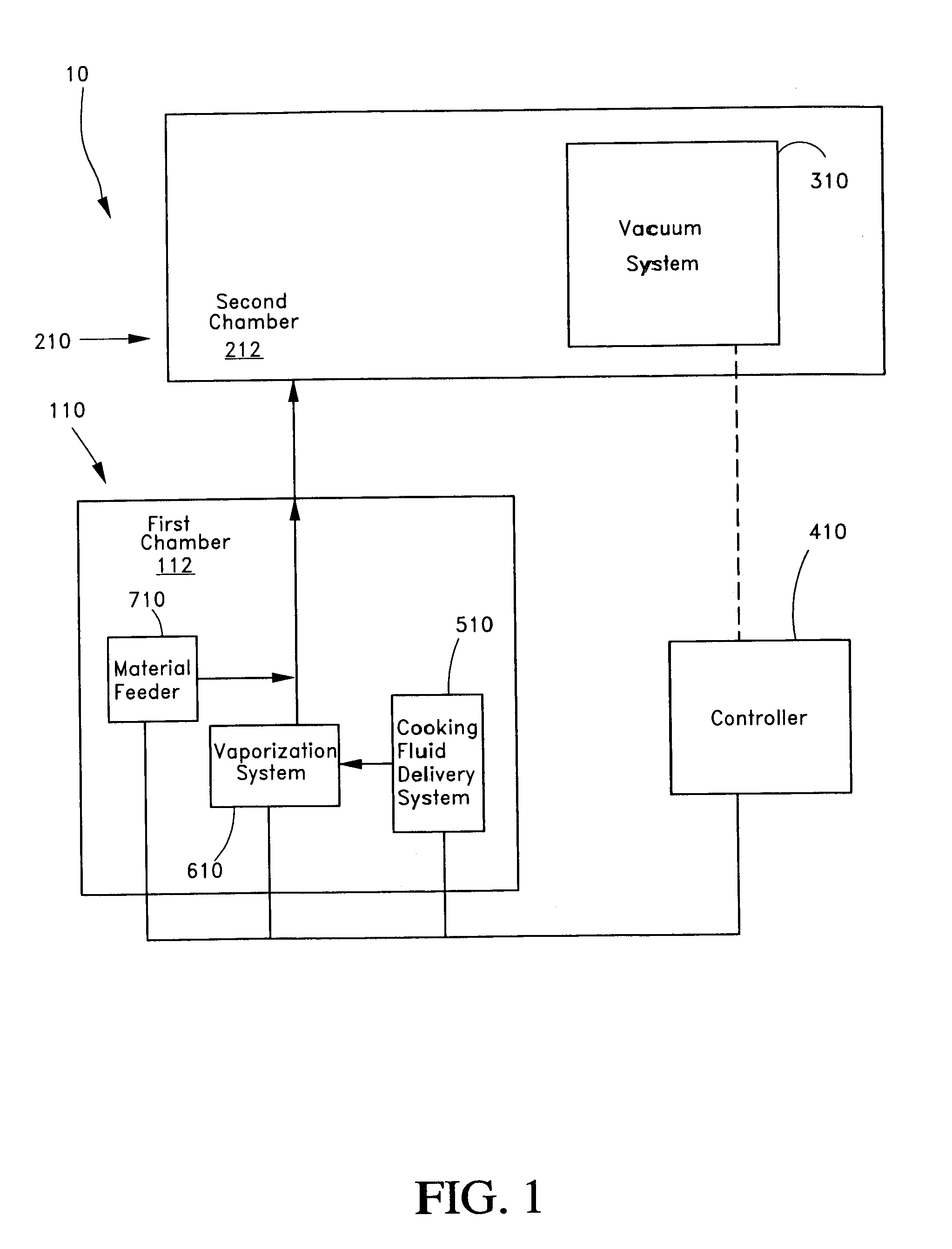
[0024]The following description and examples illustrate preferred embodiments of the present inventions in detail. Those of skill in the art will recognize that there are numerous variations and modifications of these inventions that are encompassed by its scope. Accordingly, the description of preferred embodiments should not be deemed to limit the scope of the present inventions.

[0025]“Quench gas” or “quenchant gas” as used in this specification refers to a gas that has a cooling effect on a material and may, depending upon the ambient conditions, induce a phase change in the material. As used within this specification, the term “substantially laminar” includes generally smooth fluid flows that may be completely laminar as well as flows that include turbulent portions, as described and illustrated below, and flows including incidental or transient eddies. The term “substantially free convection,” as used in this specification, includes movement of fluids (including gases) due to e...


PUM

PropertyMeasurementUnit
heightaaaaaaaaaa
heightaaaaaaaaaa
surface temperatureaaaaaaaaaa

Abstract

Nano-scale particles of materials can be produced by vaporizing the material and allowing the material to flow in a non-violently turbulent manner into thermal communication with a cooling fluid, thereby forming small particles of the material that can be in the nano-scale size range.

Description

PRIORITY INFORMATION[0001]This application is based on and claims priority to U.S. Provisional Application No. 60 / 529,724, filed Dec. 15, 2003, and U.S. Provisional Application No. 60 / 568,457, filed May 4, 2004, the entire contents of both of which is hereby expressly incorporated by reference.BACKGROUND OF THE INVENTIONS[0002]1. Field of the Inventions[0003]The inventions disclosed herein relate to the production of nano-sized particles. In particular, the inventions relate to the vaporization and condensation of material for forming nano-sized particles of the material.[0004]2. Description of the Related Art[0005]Techniques for producing nanoparticles generally fall into one of three categories, namely: mechanical, chemical or thermal processing. In mechanical processes, nanopowders are commonly made by crushing techniques such as ball milling. There are several disadvantages to this approach. The grinding media and the mill wear away and combine with the nanomaterial, contaminati...

Claims


Application Information

Patent Timeline
Patent Type & Authority Patents(United States)
IPC IPC(8): B29B9/00B22F1/054
CPCB22F1/0018B22F9/12B22F9/06B22F9/04B82Y30/00B22F1/054
Inventor CARPENTER, DOUGLAS
Owner VIVAKOR INC
Why Eureka
Try Eureka