Forge welding process

a welding process and forging technology, applied in the direction of welding apparatus, manufacturing tools, other domestic objects, etc., can solve the problems of pipe ends, difficult steps to achieve, and forming of shocks

Inactive Publication Date: 2007-10-16
SHELL OIL CO
View PDF92 Cites 21 Cited by
  • Summary
  • Abstract
  • Description
  • Claims
  • Application Information

AI Technical Summary

Benefits of technology

[0016]The improved method of forge welding tubulars according to the invention comprises heating the tubular ends to be joined in a welding chamber to a predetermined temperature while the heated tubular ends are maintained substantially aligned and parallel relative to each other at a spacing (S), whereupon the heated tubular ends are pressed against each other while a reducing shield gas is injected into the chamber, and wherein during at least part of the heat up, forge welding and/or cool down steps the positions of the tubular ends are monitored by a number of circumferentially spaced cameras which are coupled to a pyrometric and position monitoring system which automatically adjusts the position of the tubular ends relative to each other and the heat supplied to the tubular ends during the heating step until the pyrometric monitoring system indicates that the tubular ends have reached a predetermined temperature, whereupon the tubular ends are moved towards each other along a distance(S+D), which exceeds the spacing (S) monitored between the tubular ends during the heating step with a selected extra distance(D).
[0017]Preferably said extra distance(D) is selected such that the tubular ends are firmly p

Problems solved by technology

Experiments have shown that forge welding techniques are capable to generate high quality metallurgical bonds between the tubular ends, in particular if the pipe ends are flushed with a reducing gas mixture during the welding operation, but that the red-hot pipe ends are generally deformed such that upsets are formed in the region of the welding zone.
For obtaining a high quality forge weld joint it is required to keep the tubular ends fully aligned with the end faces parallel to each other at a well-defined spacing of a few millimeters only during the heat-up phase and to terminate the heat-up if the pipe ends have reached a preset temperature and to forge the tubular ends for a well-defined length and to cool them down quickly at a well defined cooling rate, which steps are difficult to accomplish at many sites where pipe ends are welded together, such as on oil rigs, pipelaying barges and many on-land sites where underground or above-ground pipelines are to be installed.
The use of a robotic transport apparatus is not practical for inspection of welds between tubulars since it requires the robotic transport apparatus to rotate around a welded tubular, which is time consuming and requires the use of a fragile robotic tool.
The device disclosed by Passarelli has the disadvantage that it is has a fixed ring-shape construction, which cannot be put readily around the tubulars and the weld at the rig floor without the danger of damaging the device or at the expense of substantial time delays.
Another disadvantage to this arrangement is the geometry of the electromagnets, the transmitter and the receiver coil, which does not provide a 100% inspection of the weld around

Method used


Image

  • Forge welding process
  • Forge welding process
  • Forge welding process

Examples


Embodiment Construction

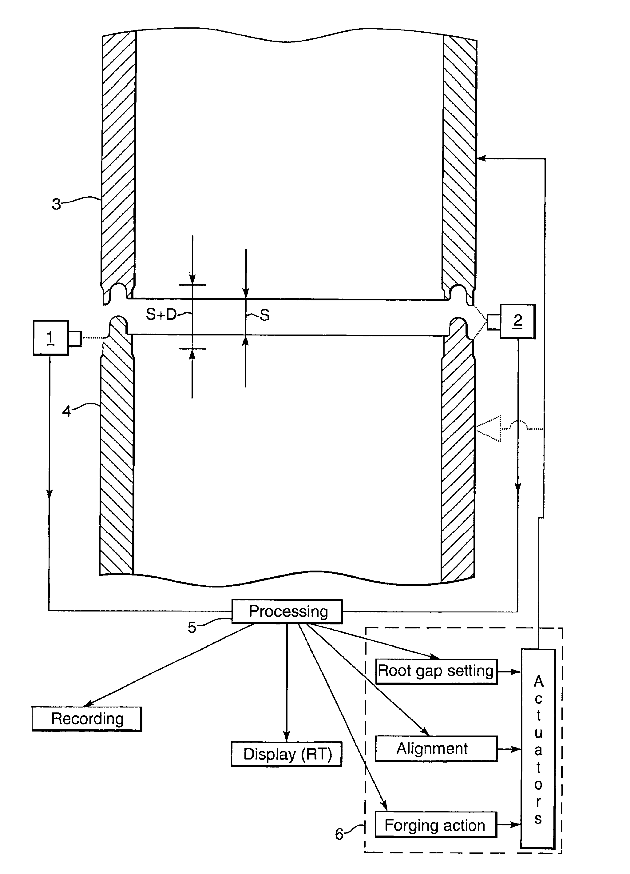
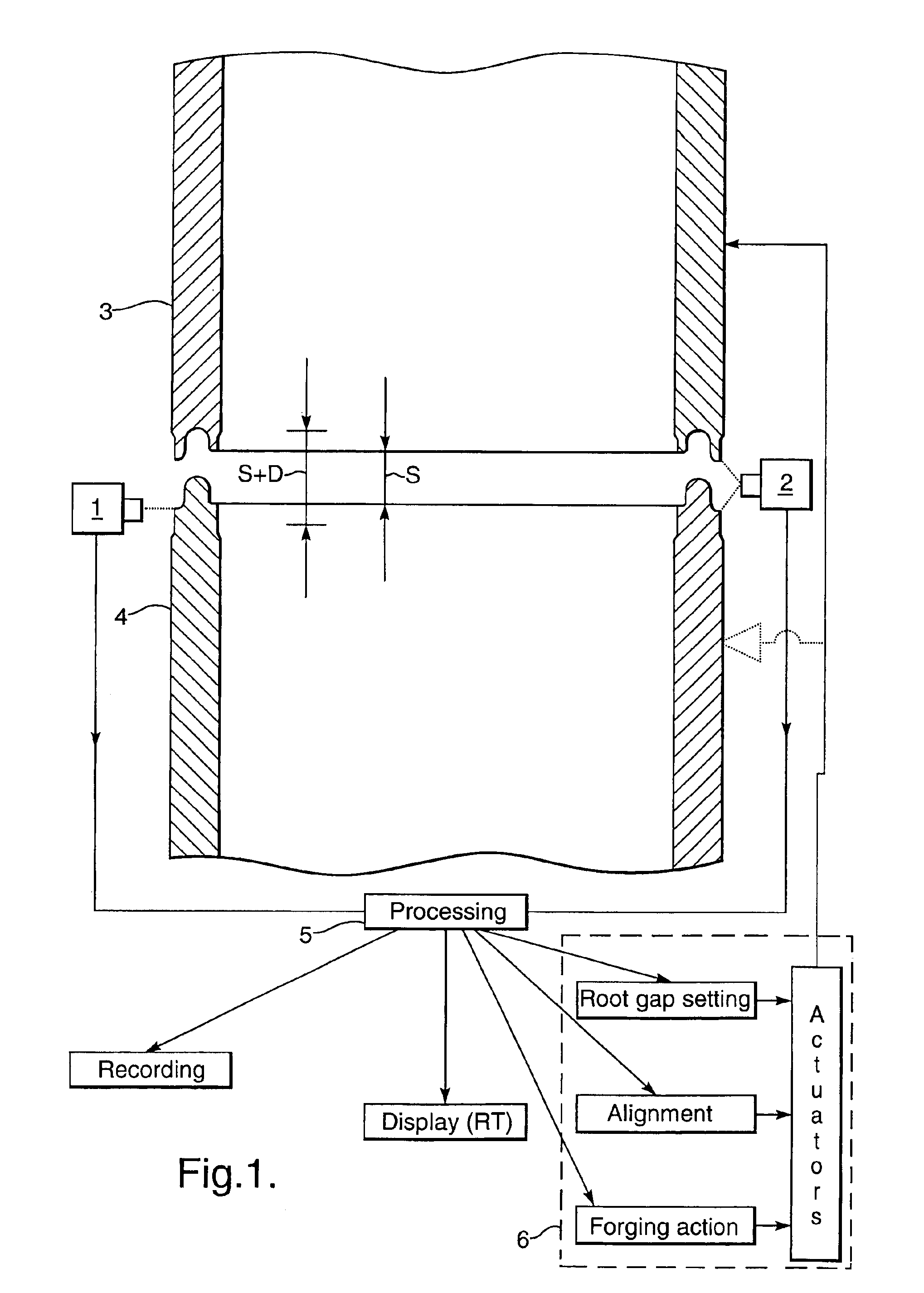
[0050]As shown in FIG. 1 the positions of the tubular ends 3 and 4 that are to be forge welded together are monitored by cameras 1 and 2 which are coupled to a camera signal processor 5 which automatically controls a gripping assembly 6, such that the spacing S between the heated tubular ends 3A and 4A is well defined during the heat up phase and the tubular ends are moved towards each other when a pyrometric control unit indicates that the tubular ends have reached a predetermined minimum and / or maximum temperature along at least a substantial part of the circumference thereof, whereupon the gripping assembly is activated to move the tubular ends 3A and 4A towards each other over a predetermined distance (S+D) which exceeds said spacing (S) with an additional distance (D) of less than a few millimeters, such that a forge weld is obtained of a substantially equal and high quality over the entire circumference of the forge welded ends and only minimal external and / or internal upsets ...


PUM

PropertyMeasurementUnit
Thicknessaaaaaaaaaa
Thicknessaaaaaaaaaa
Percent by volumeaaaaaaaaaa

Abstract

An automated method for forge welding tubulars including heating the tubular ends to be joined in a welding chamber while the heated tubular ends are maintained aligned and parallel relative to each other and at a small spacing, whereupon the heated tubular ends are pressed together while a reducing shield gas is injected into the chamber. The positions of the tubular ends are monitored by cameras which are coupled to a pyrometric and position monitoring system which automatically adjusts the position of the tubular ends relative to each other and the heat supplied to the tubular ends during the heating step until the tubular ends have reached a predetermined temperature, whereupon the tubular ends are moved towards each other along a distance which exceeds the spacing monitored between the tubular ends during the heating step with a selected extra distance, such that the tubular ends are firmly pressed against each other and the amount of external and/or internal upset of the tubular ends in the welding zone is limited to an acceptable level.

Description

FIELD OF THE INVENTION[0001]The invention relates to an improved forge welding process.BACKGROUND OF THE INVENTION[0002]Forge welding involves circumferential heating of the pipe ends that are to be joined and subsequently pressing the pipe ends together to form a metallurgical bond.[0003]A large variety of heating technologies may be used to make the pipe ends hot enough such that the metallurgical bond can be made. The heating techniques may involve electric, electromagnetic, induction, infrared, arcing and / or friction heating or combinations of these and other heating methods.[0004]When used in this specification the term forge welding is intended to encompass all techniques which involve circumferential heating of pipe ends and subsequent metallurgical bonding of the heated pipe ends, including welding techniques that are generally known as fusion or diffusion welding, friction welding, flash welding and / or butt welding.[0005]It is known from U.S. Pat. Nos. 4,566,625, 4,736,084,...

Claims


Application Information

Patent Timeline
IPC IPC(8): B23K11/02B23K11/24B23K1/00B23K9/32B23K13/01B23K20/02B23K20/26
CPCB23K1/00B23K9/32B23K20/02B23K20/26B23K13/01B23K2201/06B23K2101/06B23K11/02B23K11/0006B23K11/25
Inventor ALFORD, ROBERT ANDREWDEN BOER, JOHANNIS JOSEPHUSCOLE, ANTHONY THOMASDIMITRIADIS, KLISTHENISEFTHYMIOU, MICHALAKISGUNTURI, RAMA KRISHNA SIVAWORRALL, ROBERT NICHOLASZIJSLING, DJURRE HANSCOX, ALI JOSEPH
Owner SHELL OIL CO
Why Eureka
Try Eureka