Distributed fiber sensor based on spontaneous brilluoin scattering

Active Publication Date: 2007-10-16
NP PHOTONICS A CORP OF DELAWARE
View PDF7 Cites 92 Cited by
  • Summary
  • Abstract
  • Description
  • Claims
  • Application Information

AI Technical Summary

Benefits of technology

[0015]The present invention provides a low cost spontaneous Brillouin-based distributed fiber sensor that optically shifts the frequency of the OLO to set the Brillouin/OLO beat frequency within the

Problems solved by technology

In contrast, the Raman lines are out of the most-commonly used wavelength region for telecommunication, and fiber optic components at the Raman wavelengths are not commercially available.
However, the complexity and high cost of current implementations has prevented widespread commercialization.
However, since the frequency of spontaneous Brillouin backscattering is down-shifted by approximately 11 GHz (“the Brillouin frequency shift”) from that of a 1.55 μm pump light, the beat frequency (coherent self-heterodyne signal) between the spontaneous Brillouin backscattering and the pump light is extremely high and the signal lies out of the bandwidth of most commonly-used conventional heterodyne receivers, which requires expensive microwave coherent detection.
Since the thermal noise power of a photo receiver is proportional to the receiver bandwidth, microwave detection suffers from low sensitivity and high noise level.
To obtain an acceptable SNR (signal-to-noise ratio), the beat signal needs to be averaged over hundreds and thousands of times, which is a time-consuming process and results in measurement times of typically more than ten minutes per measurement.
Thus, it is pract

Method used


Image

  • Distributed fiber sensor based on spontaneous brilluoin scattering
  • Distributed fiber sensor based on spontaneous brilluoin scattering
  • Distributed fiber sensor based on spontaneous brilluoin scattering

Examples


Embodiment Construction

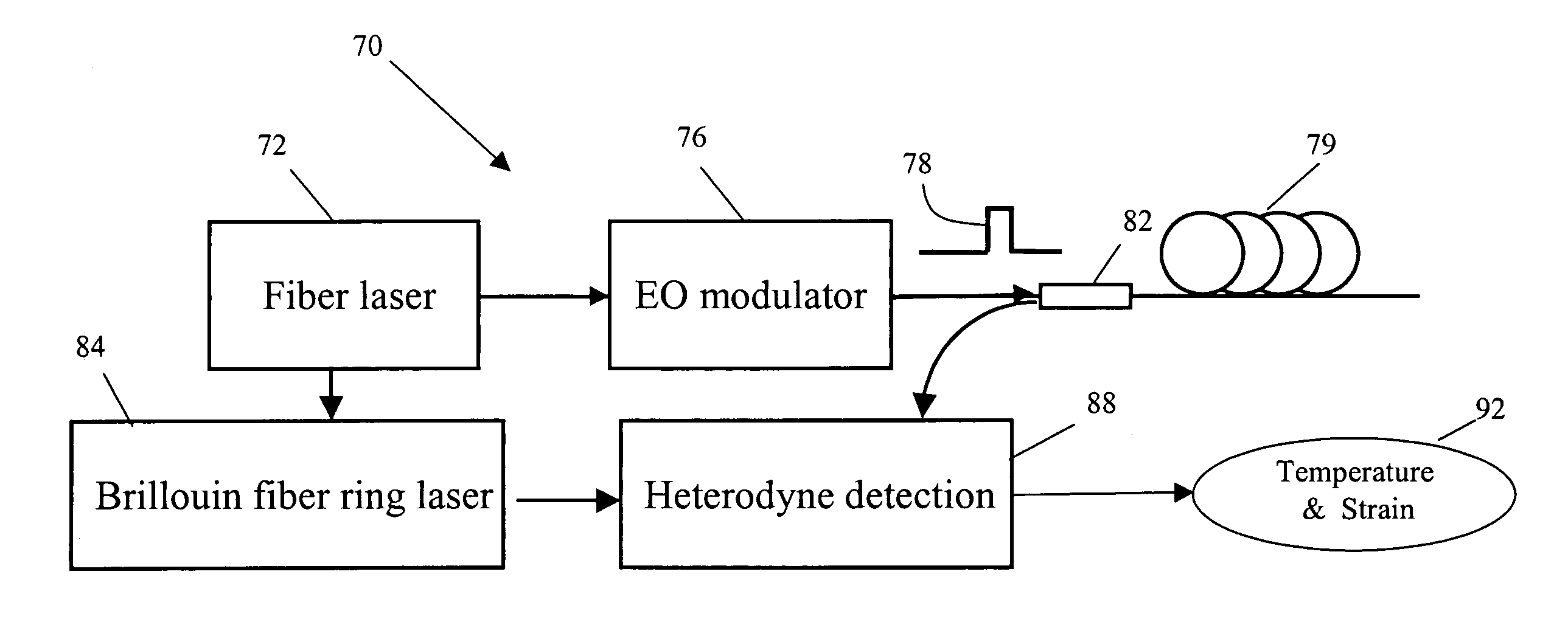
[0030]The present invention provides a low cost spontaneous Brillouin scattering-based distributed fiber sensor that is capable of real-time measurement of both temperature and strain. The use of a Brillouin fiber ring laser to optically shift the frequency of the OLO to set the Brillouin / OLO beat frequency within the bandwidth of a conventional heterodyne receiver avoids the deficiencies of existing implementations.

[0031]As shown in FIGS. 4 and 5, a spontaneous Brillouin-based distributed fiber sensor 70 includes a fiber laser 72 that generates a single-frequency output 74 having a narrow linewidth suitably centered on a wavelength in the range of 1.3 to 1.5 microns. An electro-optic (EO) modulator 76 amplitude modulates the single-frequency output to launch pulsed light 78 into a sensing fiber 79 (up to many kilometers in length) generating spontaneous Brillouin scattering (SBS) 80 with a first Brillouin frequency shift (≈11 GHz). Light is coupled in and out of the sensing fiber v...


PUM


Abstract

A distributed fiber sensor based on spontaneous Brillouin scattering uses a single-frequency fiber laser as a source and a cw Brillouin fiber ring laser as an OLO to optically shift the frequency of the OLO to set the Brillouin/OLO beat frequency within the bandwidth of a conventional heterodyne receiver. The distributed fiber sensor is capable of real-time measurement of both temperature and strain.

Description

BACKGROUND OF THE INVENTION[0001]1. Field of the Invention[0002]This invention relates to distributed fiber sensors based on spontaneous Brillouin scattering—and more specifically to a distributed fiber sensor that uses a single-frequency laser to generate the pulsed light and a Brillouin fiber ring laser to provide the optical local oscillator (OLO).[0003]2. Description of the Related Art[0004]The application of optical fiber technology to the problem of distributed sensing offers the potential ability to determine a physical parameter such as temperature or strain as a function of the position along an optical fiber cable over lengths up to tens of kilometers. Typically, the measurements are performed using optical time-domain reflectometry (OTDR), which detects pulsed of light backscattered from the optical fiber.[0005]Distributed fiber sensors based on Brillouin scattering have received attention since the Brillouin frequency shift in an optical fiber was found to linearly depen...

Claims


Application Information

Patent Timeline
IPC IPC(8): G01B9/02
CPCG01D5/35303G01B11/18G01D5/35358
Inventor GENG, JIHONGJIANG, SHIBINSPIEGELBERG, CHRISTINE
Owner NP PHOTONICS A CORP OF DELAWARE
Why Eureka
Try Eureka