Disk drives and methods allowing for dual stage actuator adaptive seek control and microactuator gain calibration

Active Publication Date: 2007-10-16
MAXTOR
View PDF3 Cites 48 Cited by
  • Summary
  • Abstract
  • Description
  • Claims
  • Application Information

AI Technical Summary

Benefits of technology

[0033]A method according to an embodiment of the present invention allows for controlling a microactuator based on a plurality of microactuator feedforward values and for tuning at least one microactuator feedforward value of the plurality of microactuator feedforward values. A method according to various embodiments of the present invention allows for scaling a microactuator feedforward control signal in accordance with a microactuator feedforward gain, for controlling the microactuator based on the scaled microactuator feedforward control signal during a seek operation, for determining a position error signal during the seek operation, and for adjusting the microactuator feedforward gain based on the

Problems solved by technology

However, in reality, the microactuator usually does not have a perfectly linear gain, so the microactuator will not move as precisely as expected based on the control signal.
Some microactuators are known to have hysteresis and nonlinearity characteristics, and their gains are known to be sensitive to temperature change.
Testing shows that some microactuators have up to 20% nonlinearity in gain from small to full scale excitation, and up to 20% change in gain for a change in temperature from 0° C. to 65° C. In addition, seek TMR may also be affected by a reference track error of a coarse actuator control loop due to modeling error, and may be affected by pivot friction of the coarse actuator.
Since the microactuator feedforward values in the related art disk drives are precomputed with the assumption that the microactuator has a linear gain and then are stored as constant va

Method used


Image

  • Disk drives and methods allowing for dual stage actuator adaptive seek control and microactuator gain calibration
  • Disk drives and methods allowing for dual stage actuator adaptive seek control and microactuator gain calibration
  • Disk drives and methods allowing for dual stage actuator adaptive seek control and microactuator gain calibration

Examples


Example

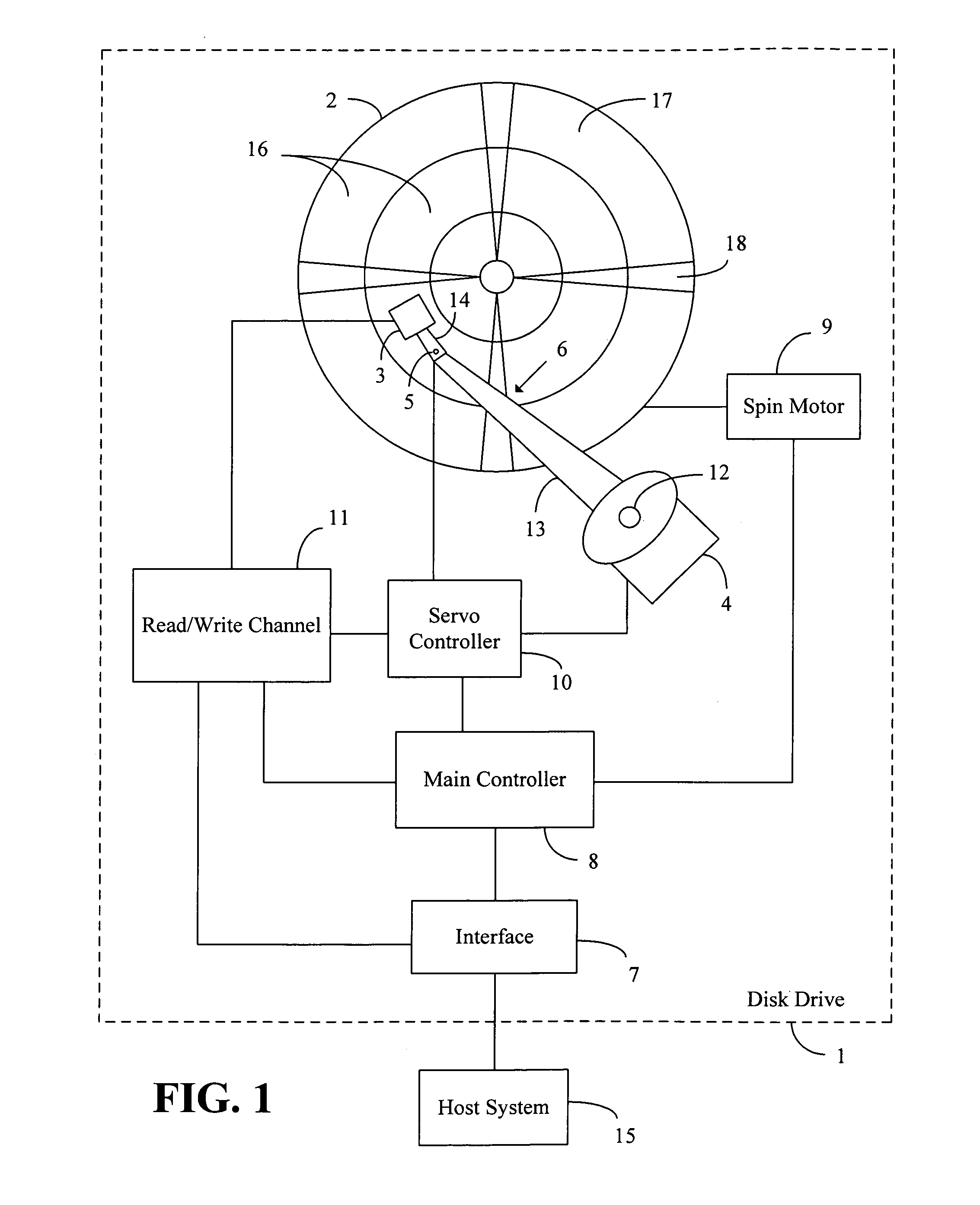
[0041]FIG. 1 illustrates a functional block diagram of a disk drive 1 of an embodiment of the present invention. The disk drive 1 comprises a disk 2, a transducer or head 3, a coarse actuator 4, a microactuator 5, an actuator arm assembly 6, an interface 7, a main controller 8, a spin motor 9, a servo controller 10, and a read / write (r / w) channel 11. The head 3 is mounted on one end of the actuator arm assembly 6, and another end of the actuator arm assembly 6 is connected to a base (not shown) of the disk drive 1 by a bearing 12.

[0042]The actuator arm assembly 6 comprises a first member 13 and a second member 14 that are interconnected by the microactuator 5. During operation, the disk 2 spins around a central axis, and the head 3 reads data from or writes data to a surface of the disk 2. The coarse actuator 4 rotates the actuator arm assembly 6 about the bearing 12 in order to control a position of the microactuator 5 and the head 3 over the disk 2. The microactuator 5 moves the s...


PUM


Abstract

A disk drive includes a disk, a head, a coarse actuator, a microactuator, and a servo controller. The microactuator positions the head relative to the disk. The coarse actuator positions the microactuator and the head relative to the disk. The servo controller controls the microactuator in accordance with a microactuator feedforward control signal that is provided by the servo controller based on a plurality of microactuator feedforward values. The servo controller tunes at least one microactuator feedforward value of the plurality of microactuator feedforward values. The servo controller scales the microactuator feedforward control signal in accordance with a microactuator feedforward gain, and the servo controller adjusts the microactuator feedforward gain based on a position error signal that is determined during a seek operation.

Description

CROSS-REFERENCE TO RELATED PATENT APPLICATIONS[0001]Embodiments of the present invention relate to U.S. Provisional Application Ser. No. 60 / 617,389, filed Oct. 8, 2004, entitled “Algorithm for Dual Stage Actuator Adaptive Seek Control and Microactuator Gain Calibration”, the contents of which are incorporated by reference herein and which is a basis for a claim of priority.BACKGROUND OF THE INVENTION[0002]1. Field of the Invention[0003]Embodiments of the present invention relate generally to disk drives and methods and, in specific embodiments, to a disk drive including a coarse actuator, a microactuator, and a servo controller, in which the servo controller is configured to tune microactuator feedforward values that are stored in a microactuator feedforward look-up table and to adjust a microactuator feedforward gain by which a microactuator feedforward control signal is scaled.[0004]2. Related Art[0005]Disk drives are widely used in computers and other electronic devices for the s...

Claims


Application Information

Patent Timeline
IPC IPC(8): G11B5/596
CPCG11B5/5552
Inventor SUN, YULI, YUNFENGGUO, LINYEAGLE, PAUL
Owner MAXTOR
Why Eureka
Try Eureka