Package filter and combiner network

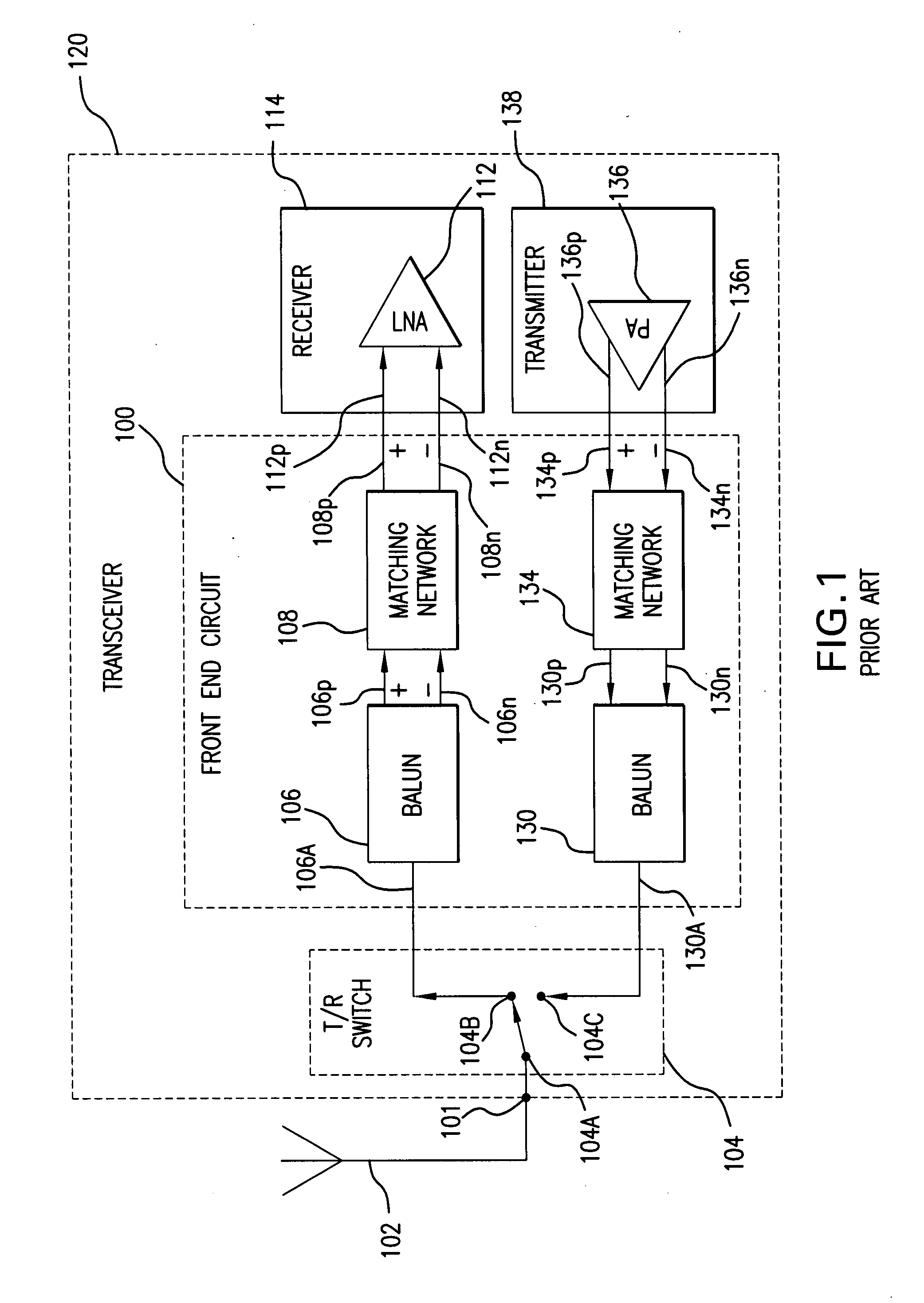
a technology of combiner network and filter, which is applied in the direction of transmission, coupling device, electrical apparatus, etc., can solve the problems of low sensitivity, low sensitivity, and inefficient tr switch 104 typical tr switch can be constructed from pin diodes, etc., to achieve optimum power and efficiency, superior functionality, and good sensitivity

Inactive Publication Date: 2007-10-16
AVAGO TECH WIRELESS IP SINGAPORE PTE +1
View PDF20 Cites 105 Cited by
  • Summary
  • Abstract
  • Description
  • Claims
  • Application Information

AI Technical Summary

Benefits of technology

[0037]Yet another advantage of the present invention is that on-board tuning is not required, which is a time-to-market benefit. Optimum power and efficiency can be achieved without need of on-board tuning.
[0038]Combining a single-ended LNA and the Balun within the package, provides the differential input on chip, which is required for good sensitivity relative to substrate noise on chip.
[0039]An integrated antenna filter in a high-Q (quality factor), low-loss package environment makes it possible to create a strip line filter that ac

Problems solved by technology

The TR switch is located off the package because of size limitations and because the TR switch is an active component (e.g., transistor, diode or integrated circuit).
Further, the typical TR switch 104 can be constructed from PIN diodes and can be very inefficient because a solid state TR switch 104 requires a high current to produce a low resistance signal path in at least one of the receive signal path or the transmit signal path.
High current use is not optimum for mobile ap

Method used


Image

  • Package filter and combiner network
  • Package filter and combiner network
  • Package filter and combiner network

Examples


Embodiment Construction

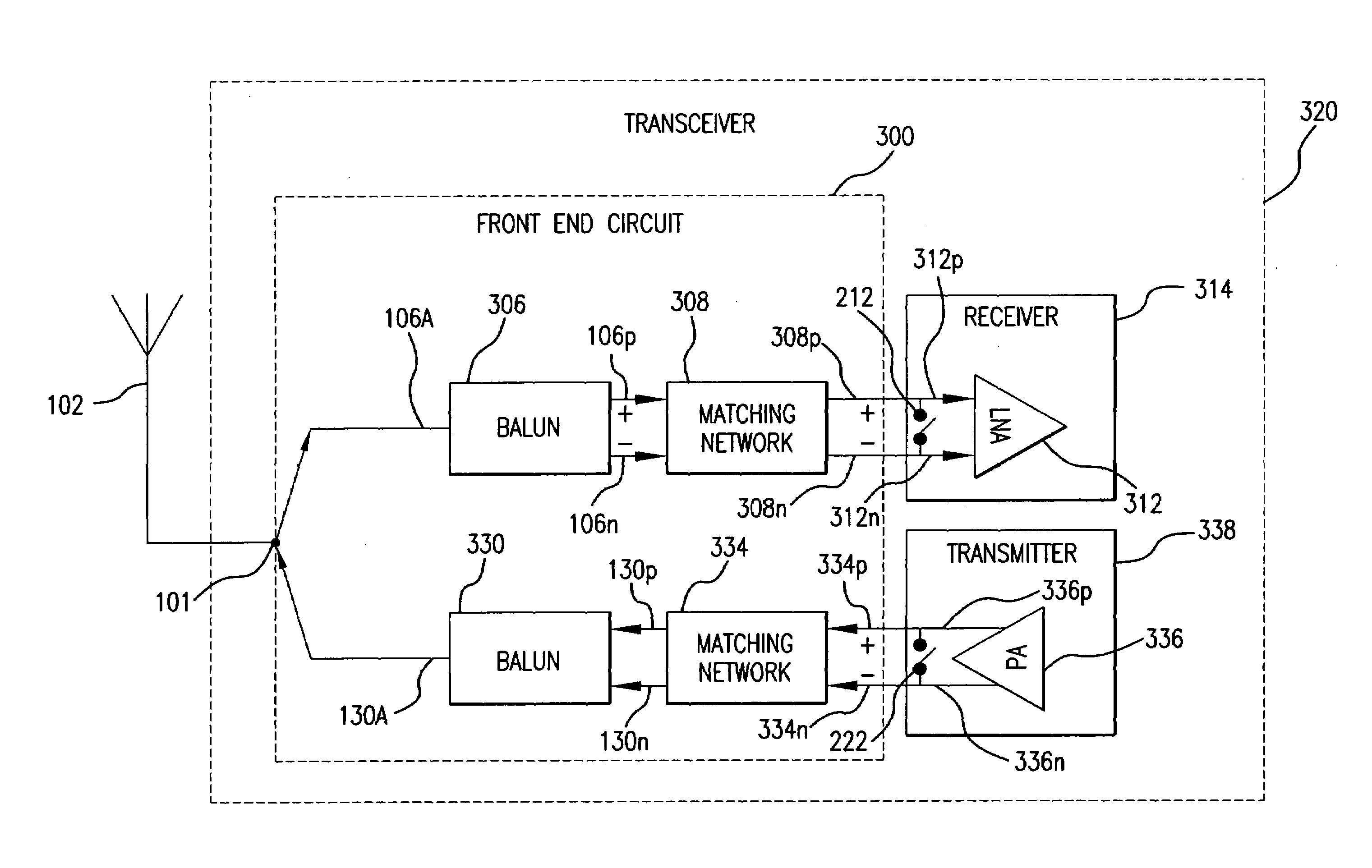
[0059]Several exemplary embodiments of a packaged, transceiver front-end circuit will now be described. It will be apparent to those skilled in the art that the present invention may be practiced without some or all of the specific details set forth herein

[0060]Modern portable transceiver systems are constantly being improved upon by incorporating ever-increasing capabilities, reduced power consumption and reduced physical size. The additional capabilities and reduction in power consumption are often achieved through increased integration. The resulting highly integrated transceivers must also have increased performance e.g., improved noise performance, improved receiver sensitivity and increased transmit power efficiency, while also providing a reduced cost and other improvements. Highly integrated transceivers are used in many common applications that people can touch, hold in their hands, put in their pockets and briefcases, on their desks, in their houses and in new applications...


PUM


Abstract

A transceiver front end circuit includes an antenna terminal capable of being coupled to an antenna. A first balun circuit has a single input that is coupled to the antenna terminal, and a pair of balanced outputs coupled to a corresponding pair of balanced receiver inputs. The first balun circuit matches an input impedance of the pair of balanced receiver inputs and substantially phase shifts the input reflection coefficient of the pair of balanced receiver inputs by about 180-degrees. A second balun circuit has a single output coupled to the antenna terminal and a pair of balanced inputs coupled to a corresponding pair of balanced transmitter outputs. The second balun circuit matches an output impedance of the pair of balanced transmitter outputs and substantially phase shifts the output reflection coefficient of the pair of balanced transmitter outputs by about 180-degrees. The first balun circuit and the second balun circuit can be contained within a single package. A first shunt switch can be coupled across the pair of receiver inputs. A second shunt switch can be coupled across the pair of transmitter outputs.

Description

CROSS REFERENCE TO RELATED APPLICATIONS[0001]This application claims priority from U.S. Provisional Patent Application No. 60 / 381,387 filed on May 15, 2002 and entitled “Package Filter Combiner Network,” by Inventor Tom McKay, which is incorporated herein by reference in its entirety.BACKGROUND OF THE INVENTION[0002]1. Field of the Invention[0003]The present invention relates generally to transceiver front-end circuits and more specifically to a highly integrated transceiver front-end circuitry that couples a single antenna port to both a balanced receiver input and a balanced transmitter output.[0004]2. Description of the Related Art[0005]Highly integrated radios typically have differential inputs on the receiver and differential outputs on the transmitter. The differential inputs on the receiver allow the receiver to reject common mode signals (e.g., noise) and variations. By way of example, a differential input can detect input differential signals that a single ended (i.e., a no...

Claims


Application Information

Patent Timeline
IPC IPC(8): H04B1/44
CPCH04B1/0458H04B1/44H04B1/18
Inventor MCKAY, TOM
Owner AVAGO TECH WIRELESS IP SINGAPORE PTE
Why Eureka
Try Eureka