Fluidized-bed gasification and combustion furnace

a technology of flue gasification and combustion furnace, which is applied in the mechanical details of gasifiers, combustible gas production, sustainable manufacturing/processing, etc., can solve the problems of undeveloped technology for handling particles having a high temperature and containing unburned substances, fatal damage to a stable operation of the whole system, and inability to meet technical difficulties, etc., to achieve the effect of improving the gasification rate, reducing the amount of air supplied to the furnace, and increasing the heating value of gas per unit volum

Inactive Publication Date: 2007-10-23
EBARA CORP
View PDF31 Cites 9 Cited by
  • Summary
  • Abstract
  • Description
  • Claims
  • Application Information

AI Technical Summary

Benefits of technology

[0020]In order to solve the above problems, it is an object of the present invention to provide a fluidized-bed gasification and combustion furnace in which a combustion furnace to be separately installed is not required, and a gasification furnace and a combustion furnace are integrated with each other. Hence, a space necessary for its installation becomes small, and even if fuel generates a large amount of char like coal, the amount of char to be transferred can be easily controlled, and there is no clogging trouble in the pipes. In addition, a fluidized-bed gasification and combustion furnace is provided in which char can be combusted in a simple facility, combustion heat of char can be utilized as a heat source for gasification, and the bed temperature in the combustion furnace can be easily and accurately controlled. In addition, a fluidized-bed gasification and combustion furnace is provided in which clinker is not formed, and even if fuel contains incombustible material having an irregular shape, such fuel can be used and thus a variety of fuel can be utilized, and high efficiency can be obtained, and the amount of harmful material discharged from the furnace is extremely small to allow the furnace to be suitable for environmental conservation.
[0021]Further, another object of the present invention is to provide a fluidized-bed gasification and combustion furnace which is a fluidized-bed coal boiler which can use various kinds of coal without changing the arrangement of the heat transfer surfaces in the boiler, i.e. reconstruction of the boiler.

Problems solved by technology

However, the latter method requires a technology for circulating a large amount of heating medium having a high temperature from the gasification furnace to the char combustion furnace.
However, this requires a handling technology for particles having a high temperature and containing unburned substances, so that this encounters technically difficult problems.
The reason why the topping-cycle system incorporating the pressurized fluidized-bed combustion furnace has not been put to practical use yet is that the technology for handling the particles having a high temperature and containing unburned substances has not been developed.
In such a structure in which the char combustion furnace and the gasification furnace are disposed adjacent to each other, since the fluidized medium is circulated between the char combustion furnace and the gasification furnace, both of the furnaces have a relationship to each other, and hence the fluctuation of each bed temperature may cause fatal damage to a stable operation of the whole system.
However, control of the amount of char to be combusted by controlling the amount of oxygen has a slow response speed, stable control is difficult, and the bed temperature runs out of control.
As a result, there is a probability that the fluidized medium and ashes are melted and the fluidized-bed cannot be maintained, resulting in stoppage of the operation.
However, if the bed temperature of the char combustion furnace is excessively high, then clinker is formed.
Therefore, there is a great limitation to change the kind of coal without reconstruction of the boiler, and if the kind of coal is greatly changed, the reconstruction of the boiler has been unavoidably conducted.
This is because excessive heat transfer surfaces relative to the amount of heat recovery lead to lowering the furnace temperature, causing poor combustion and deteriorating the environment by combustion gas.
Conversely, shortage of the heat transfer surfaces leads to raising the furnace temperature and causing clinker formation due to melting of ashes or agglomeration due to aggregation of the fluidized medium.

Method used


Image

  • Fluidized-bed gasification and combustion furnace
  • Fluidized-bed gasification and combustion furnace
  • Fluidized-bed gasification and combustion furnace

Examples


Embodiment Construction

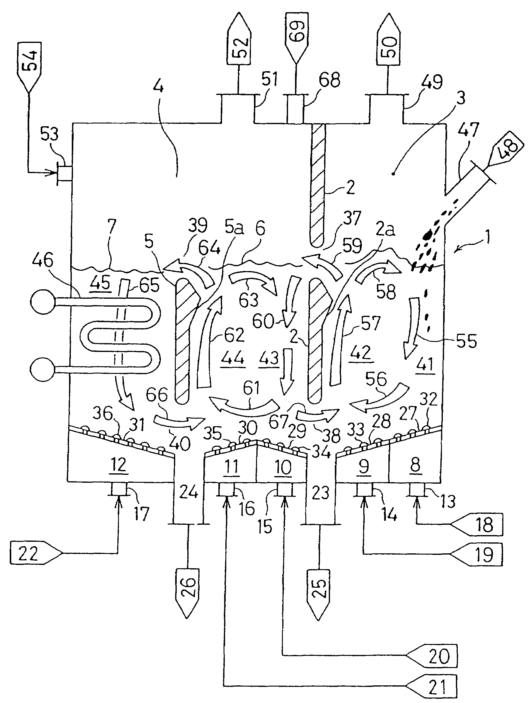
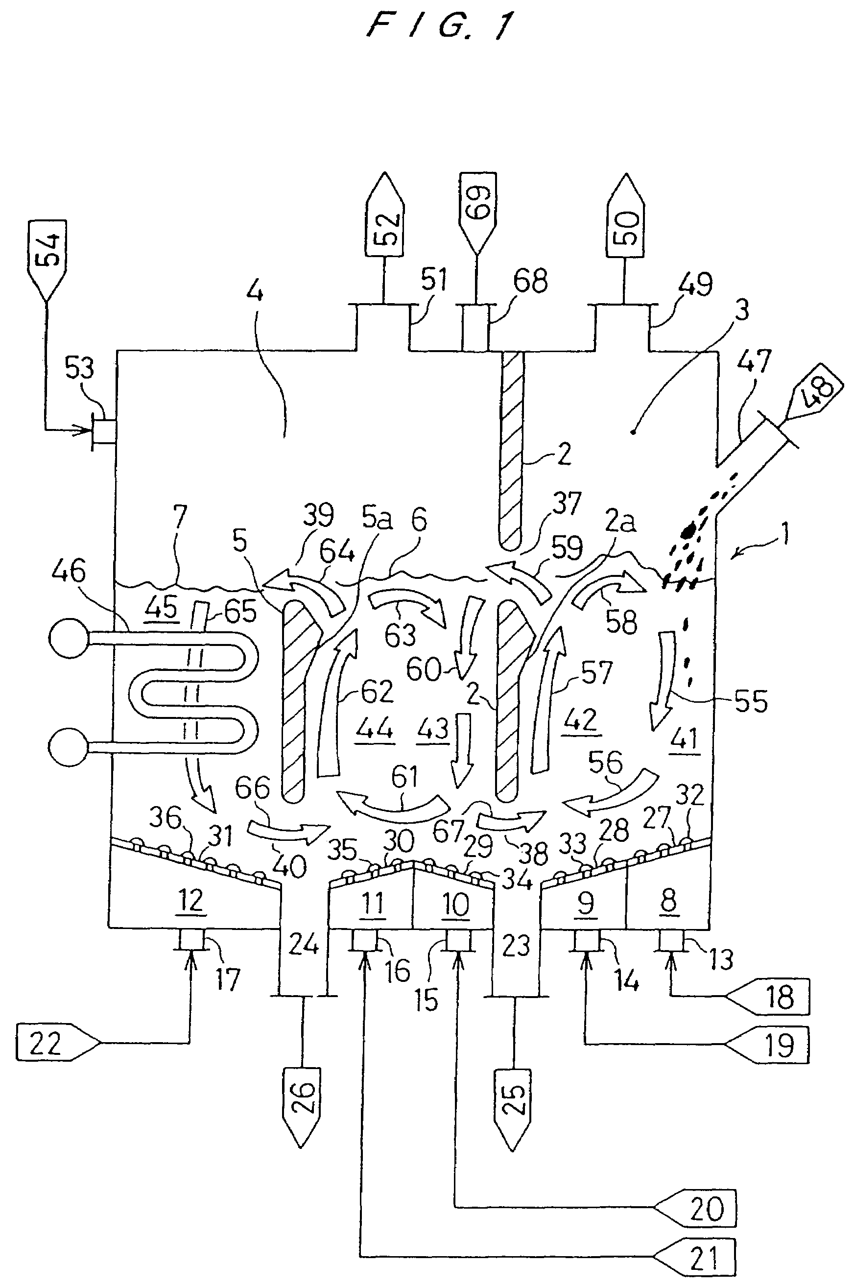
[0082]FIG. 1 is a vertical cross-sectional view of a fluidized-bed gasification and combustion furnace according to the present invention. A fluidized-bed furnace 1 according to this embodiment has a substantially rectangular shape in a horizontal cross-section. As shown in FIG. 1, the interior of the fluidized-bed furnace 1 is divided into a gasification furnace 3 and a combustion furnace 4 by a first partition wall 2. The first partition wall 2 has an upper opening 37 and a lower opening 38, and the gasification furnace 3 and the combustion furnace 4 connect with each other through the upper and lower openings 37, 38. The gasification furnace 3 has a gas discharging port 49 from which a produced gas 50 is discharged.

[0083]On the other hand, the combustion furnace 4 is further divided into a main combustion chamber 6 and a heat recovery chamber 7 by a second partition wall 5. However, the interior of the combustion furnace 4 is not divided at upper part thereof, and the main combus...


PUM

PropertyMeasurementUnit
temperatureaaaaaaaaaa

Abstract

A gasification furnace and a combustion furnace are integrated with each other to form a single fluidized-bed gasification and combustion furnace in which unburned char generated in the gasification furnace is combusted in the combustion furnace, and the thus generated heat of combustion is utilized as a heat source for gasification. The fluidized-bed gasification and combustion furnace (1) comprises a gasification furnace (3) and a combustion furnace (4) which are divided by a first partition wall (2). In the gasification furnace (3), a revolving flow of the fluidized medium is formed by diffusion devices (32, 33) provided on furnace bottoms, and an upward flow of the fluidized medium partly flows in the combustion furnace (4). The combustion furnace (4) is divided into a main partition wall (5). In the main combustion chamber (6), a revolving flow of the fluidized medium is formed by diffusion devices (34, 35) provided on furnace bottoms, and an upward flow of the fluidized medium partly flows in the heat recovery chamber (7).

Description

[0001]This application is a continuation application of U.S. application Ser. No. 09 / 530,703, filed May 4, 2000 now abandoned, which is a national stage application of International application No. PCT / JP97 / 04011, filed Nov. 4, 1997, now pending.TECHNICAL FIELD[0002]The present invention relates to a fluidized-bed gasification and combustion furnace which integrates a fluidized-bed gasification furnace and a fluidized-bed combustion furnace into a single structure.BACKGROUND ART[0003]Efforts for generating electricity at a high efficiency using coal have been made. As one of the efforts, there has been proposed a topping-cycle system which incorporates a pressurized fluidized-bed combustion furnace as shown in FIG. 14. In this system, coal is first gasified in a fluidized-bed gasification furnace 501. At this time, combustible components composed mainly of carbon (i.e., the so-called char produced in the gasification furnace 501) is combusted in a char combustion furnace 502 differe...

Claims


Application Information

Patent Timeline
Patent Type & Authority Patents(United States)
IPC IPC(8): C01B3/32
CPCC10J3/463C10J3/721C10J3/86F17C11/007C10J2200/09C10J2200/158C10J2300/1637C10J2300/165C10J2300/1884C10J2300/1892C10J2300/093C10K3/003Y02P20/10
Inventor NAGATO, SHUICHIOSHITA, TAKAHIROMIYOSHI, NORIHISATOYODA, SEIICHIROHOSODA, SHUGOKASHIMA, NOBUTAKANARUSE, KATSUTOSHI
Owner EBARA CORP
Why Eureka
Try Eureka