Honeycomb structure and method of manufacturing the same

a technology of honeycomb and end surface, which is applied in the direction of machines/engines, ceramic extrusion dies, constructions, etc., can solve the problems of deterioration of fuel efficiency of diesel engines, difficulty in forming the parts gathered or bonded in the end surface with good precision, and achieve the effect of restoring the plasticity of non-fired porous bodies

Inactive Publication Date: 2007-10-23
NGK INSULATORS LTD
View PDF17 Cites 6 Cited by
  • Summary
  • Abstract
  • Description
  • Claims
  • Application Information

AI Technical Summary

Benefits of technology

[0027]In the method of manufacturing the honeycomb structure described above, it is preferable that the method further comprises the steps of: adding water to the corresponding first and / or second end surface of the non-fired porous body to restore plasticity of the non-fired porous body before changing the shape of the first and / or second fluid channel.

Problems solved by technology

This has caused problems that the pressure loss of the honeycomb filter 31 increases and that output drop and deterioration of fuel efficiency of the diesel engine are caused.
However, for the above-described honeycomb filter, it is difficult to form the portions gathered or bonded in the end surface with good precision, and there has been a problem that gaps are easily formed in the bonded portions and the exhaust gas to be purified is discharged through the gaps of the bonded portions without being purified.
There has also been a problem that the bonded portions have low mechanical strengths and are broken by vibration or pressure of the exhaust gas.
This has caused a problem that the pressure loss of the end surface on the inflow side increases.

Method used


Image

  • Honeycomb structure and method of manufacturing the same
  • Honeycomb structure and method of manufacturing the same
  • Honeycomb structure and method of manufacturing the same

Examples


example 1

[0115]First, the foaming resin was added as the pore former to silica, kaolin, talc, and alumina which were cordierite raw materials, further the binder, dispersant, and water were added, and the materials were kneaded to form the clay-like raw material. The obtained raw material was extruded / formed by the use of the die for extruding the honeycomb structure having the predetermined shape to form the non-fired porous body in which a plurality of fluid channels extending to the second end surface from the first end surface were formed.

[0116]Next, the obtained non-fired porous body was dried by a combination of microwave drying or dielectric drying with hot air drying, and the dried non-fired porous body was cut in a predetermined length.

[0117]The polyester film was attached to the end surface of the non-fired porous body obtained in this manner, and the holes were made in the polyester film by the NC scannable laser device so that the predetermined fluid channel (second fluid channel...

example 2

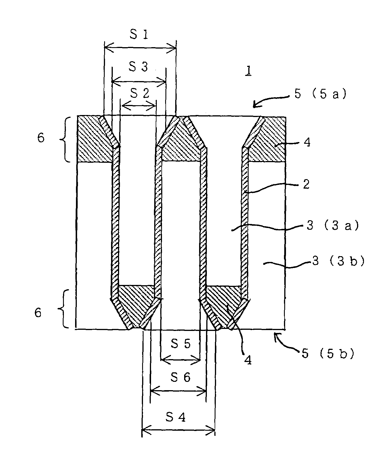
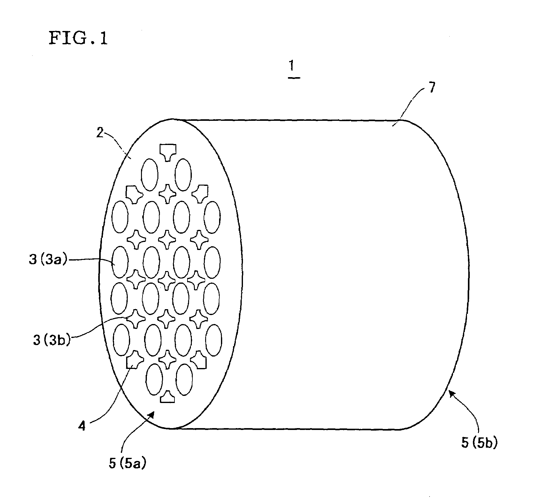
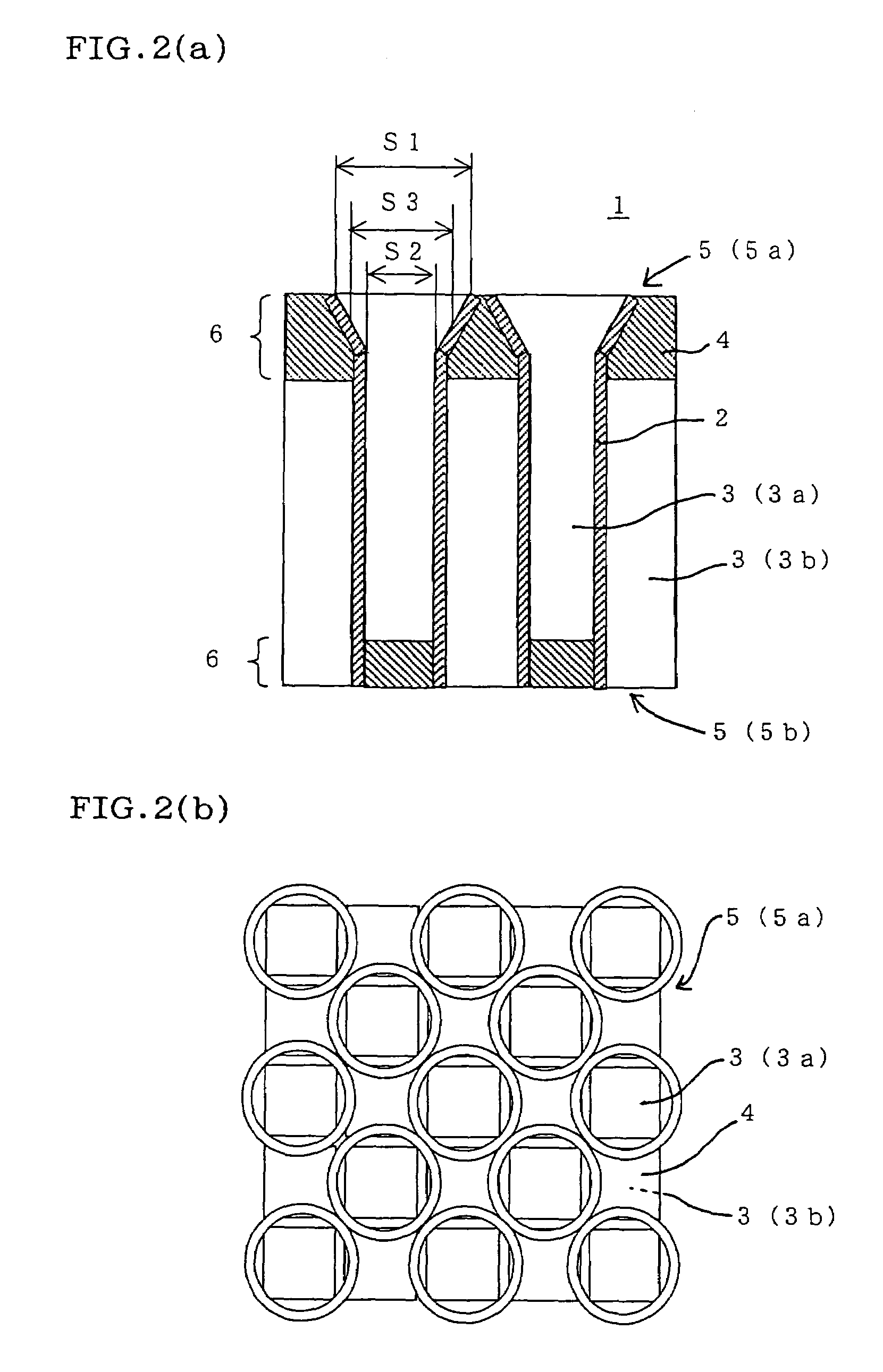
[0126]In the same manner as in the manufacturing of the honeycomb structure of Example 1, a honeycomb structure (Example 2) was manufactured in which the diameter of each of the first and second end surfaces was set to about 144 mm, the length in the flow direction of the fluid was about 152 mm, the shape of the section vertical to the central axes of the first and second fluid channels was square, and the thickness of the porous body in the portion constituting the inner wall of each fluid channel was about 0.3 mm (0.012 inch). For the honeycomb structure of the present embodiment, the interval (cell pitch) between the adjacent fluid channels was about 1.5 mm, and 300 fluid channels were formed per square inch in the section vertical to the central axis of the honeycomb structure. Moreover, for the first end surface, the fluid channels (first fluid channels) other than the channels in which the plugging material was charged were deformed into the shape in which the opening area (ar...


PUM

PropertyMeasurementUnit
mass %aaaaaaaaaa
mass %aaaaaaaaaa
mass %aaaaaaaaaa

Abstract

There are disclosed a honeycomb structure which is preferably usable as a filter, for example, for trapping particulates in an exhaust gas of an internal combustion engine, boiler or the like or for filtering liquids such as city water and sewage and in which an increase of a pressure loss at a use time is inhibited. A honeycomb structure 1 comprises: two end surfaces 5 consisting of first and second end surfaces; a porous body 2 in which a plurality of fluid channels 3 extending to a second end surface 5b from a first end surface 5a are formed; and plugging members 4 for plugging end portions 6 on end surfaces 5 side of the fluid channels 3. One or more of first fluid channels 3a are formed in a shape in which an opening area (area (S1)) in the first end surface 5a is larger than a sectional area (area (S2)) vertical to a central axis in a position in a predetermined depth from the first end surface 5a and in which a sectional area (area (S3)) vertical to the central axis in a middle between the first end surface 5a and the position in the predetermined depth gradually decreases to the area (S2) from the area (S1).

Description

BACKGROUND OF THE INVENTION[0001]1. Field of the Invention[0002]The present invention relates to a honeycomb structure and a method of manufacturing the honeycomb structure, particularly to a honeycomb structure which is preferably usable as a filter, for example, for trapping particulates in an exhaust gas of an internal combustion engine, boiler or the like or for filtering liquids such as city water and sewage and in which an increase of a pressure loss at a use time is inhibited, and a method of manufacturing the honeycomb structure.[0003]2. Description of the Related Art[0004]There has been increasingly a need for removing particulates and toxic materials from an exhaust gas of an internal combustion engine, boiler or the like in consideration of an influence on an environment. Especially, regulations on removal of particulate materials exhausted from diesel engines have tended to be reinforced in Europe, America, and Japan, and a honeycomb filter in which a honeycomb structure...

Claims


Application Information

Patent Timeline
Patent Type & Authority Patents(United States)
IPC IPC(8): B01D39/00B01D39/20B01D53/94B28B3/26B28B11/00F01N3/022F01N3/28
CPCB01D53/9454B28B11/006F01N3/0222Y10T428/24157Y02T10/20Y02T10/22Y10T428/24149F01N3/2828Y02T10/12
Inventor ICHIKAWA, YUKIHITO
Owner NGK INSULATORS LTD
Why Eureka
Try Eureka