Hand-held fluid analyzer

a fluid analyzer and hand-held technology, applied in the field of disposable, can solve the problems of not providing means that prevent the reduced-diameter ampoule from tilting within the housing, and achieve the effect of facilitating visual observation of color changes and enhancing the ability of users to visually

Active Publication Date: 2007-10-23
BOUT TIME MARKETING LLC
View PDF18 Cites 18 Cited by
  • Summary
  • Abstract
  • Description
  • Claims
  • Application Information

AI Technical Summary

Benefits of technology

[0023]In a first embodiment, the diameter of the ampoule is less than the diameter of the lumen of the housing to provide a radial space therebetween for safety purposes. Moreover, the ampoule is only about half-filled with indicator reagent to reduce the resistance to fluid flow therethrough after the ampoule has been ruptured.
[0068]Another object is to provide a color contrast surface behind the indicator reagent to further facilitate visual observation of color changes in said indicator reagent.

Problems solved by technology

In the first embodiment, a pair of porous filter members flank the ampoule but no means are provided that prevent the reduced-diameter ampoule from tilting within the housing.

Method used


Image

  • Hand-held fluid analyzer
  • Hand-held fluid analyzer
  • Hand-held fluid analyzer

Examples


first embodiment

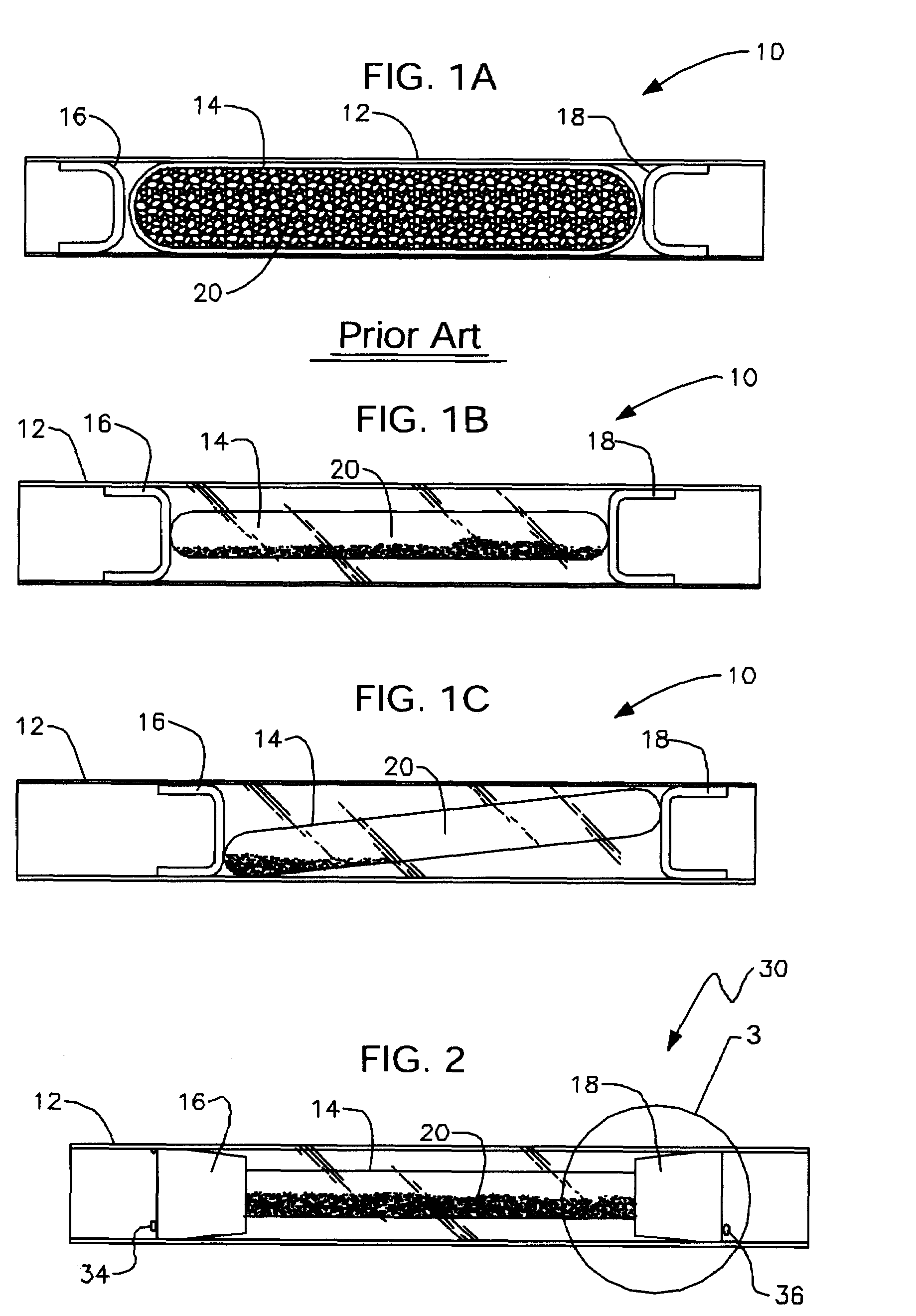
[0108]FIG. 1B depicts this invention. The diameter of glass ampoule 14 is reduced so that space is provided between vinyl housing 12 and glass ampoule 14. Thus, there is an increased measure of protection from glass shards, as compared to the patented embodiment of FIG. 1A. Moreover, ampoule 14, in the improved embodiment of FIG. 1B, is no longer completely filled. Instead it is about half full to make it easier to blow through detector 10 when ampoule 14 has been broken.

[0109]However, as indicated in FIG. 1C, one or both of the filters at the opposite ends of the reduced-diameter ampoule of FIG. 1B may slip from their initial positions, allowing ampoule 14 to become tilted, or canted, within the substance detector housing. When this occurs, the tilt of the ampoule causes the chemical grains therewithin to tend to accumulate toward one end of the ampoule. If the accumulation becomes excessive, it can alter the effectiveness of the indicator.

[0110]Moreover, when ampoule 14 is oblique...

second embodiment

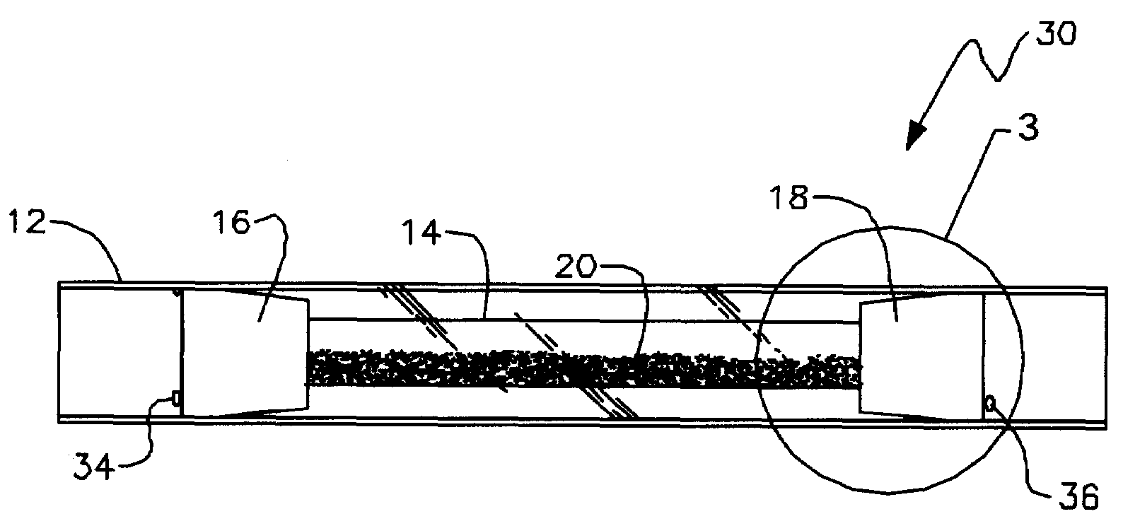
[0117]The canted-ampoule problem is resolved by this invention, denoted as a whole by the reference numeral 30 in FIG. 2. The longitudinal axis of symmetry of ampoule 14 is coincident with a longitudinal axis of symmetry of housing 12, with the result that indicator reagent 20 is evenly distributed within ampoule 14, even though the amount of said indicator reagent is only about half of the amount used in prior art detector 10 of FIG. 1A.

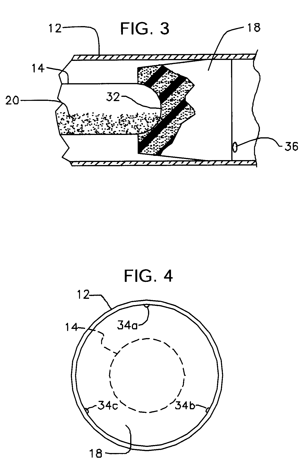
[0118]Centering of ampoule 14 as depicted in FIG. 2 is accomplished by forming concavity 32 in the inboard end of each filter 16, 18. FIG. 3 depicts concavity 32 formed in filter 18; the concavity formed in filter 16 has the same construction. As indicated in FIG. 3, the radius of curvature of each concavity is equal and complementary to the radius of curvature of the rounded ends of ampoule 14 so that the ends of said ampoule are perfectly seated within their respective concavities in stable, non-shifting relationship therewith. This structure main...

third embodiment

[0121]However, the concavities do not solve the problem associated with unwanted longitudinal displacement of the filters of the type depicted in FIG. 1. The solution to that problem is embodied in the invention which is also depicted in FIG. 2. At least one radially inwardly projecting protrusion 34 is formed in deformable housing 12 in outboard relation to filter 16 and at least one radially inwardly projecting protrusion 36 is formed in deformable housing 12 in outboard relation to filter 18. Each protrusion 34, 36 provides a detent means that prevents sliding of said filters away from ampoule 14. Thus, ampoule 14 prevents travel of the filters in an inboard direction and detents 34, 36 prevent travel of the filters in an outboard direction.

[0122]As depicted in FIG. 4, multiple protrusions may be formed in said deformable housing 12. In the example of FIG. 4, three protrusions 34a, 34b, and 34c are disposed in equidistantly and circumferentially spaced apart relation to one anoth...


PUM

PropertyMeasurementUnit
ineffective timeaaaaaaaaaa
timeaaaaaaaaaa
flexibleaaaaaaaaaa

Abstract

A hand-held device detects the presence of a preselected substance in the breath. A deformable housing forms a test chamber for interacting an indicator reagent with the breath. An ampoule positioned inside the housing is ruptured by manual pressure through the walls of the housing. The contents of the ruptured ampoule are exposed to the breath introduced into the chamber. The presence of a substance in the breath causes the indicator reagent to undergo a visually ascertainable change. The ampoule is secured within the housing by a pair of filter plugs having inboard concavities to receive the rounded ends of the ampoule to center it within the housing, and plural detents prevent slippage of the filters. Additional embodiments lower the user's risk of being cut by glass shards, prevent reagent inhalation, enhance the visual aspects of the device, and physically indicate the presence of breath flowing through the device.

Description

BACKGROUND OF INVENTION[0001]1. Field of the Invention[0002]This invention relates, generally, to disposable, field usable detectors for detecting the presence of substances in test fluids by use of indicator chemistry. More specifically, this invention relates to single-use, disposable devices for efficiently detecting the presence of controlled or other substances in the breath or other fluid by employing chemical indicators that react in a certain prescribed manner to the presence of such substance.[0003]2. Description of the Prior Art[0004]U.S. Pat. No. 4,740,475, awarded Apr. 26, 1988 to Paul, discloses an alcohol detection device that addresses the problem of “chemical indicator freshness.” The indicator reagents typically used in these devices tend to deteriorate when exposed to air or moisture prior to use. Thus, the devices have to be handled and stored carefully. The reliability of these types of tests is questionable in the event of breakage or improper sealing.[0005]Howe...

Claims


Application Information

Patent Timeline
Patent Type & Authority Patents(United States)
IPC IPC(8): B32B5/02B32B27/04B32B27/12G01J1/48G01N7/00
CPCA61B5/097A61B5/4833G01J1/50G01N21/783G01N21/293Y10T436/255Y10T436/25875Y10T436/25
Inventor MARTIN, LAWRENCE
Owner BOUT TIME MARKETING LLC
Why Eureka
Try Eureka