DC-DC converter with load intensity control method

a dc-dc converter and load intensity control technology, applied in pulse technique, process and machine control, instruments, etc., can solve the problems of reducing efficiency and losing switching, and achieve the effect of improving the efficiency of dc-dc converters and minimizing unnecessary switching

Inactive Publication Date: 2007-10-23
SAMSUNG ELECTRONICS CO LTD
View PDF14 Cites 13 Cited by
  • Summary
  • Abstract
  • Description
  • Claims
  • Application Information

AI Technical Summary

Benefits of technology

[0017]Accordingly, it is an aspect of the present invention to provide a DC-DC converter to minimize an unnecessary switching which occurs when a light electric load is connected to improve an efficiency of the DC-DC converter.
[0018]It is another aspect of the present invention to provide a method of controlling a DC-DC converter to minimize unnecessary switching, thereby improving the efficiency of the DC-DC converter.
[0022]According to an aspect of the invention, the controller reduces the number of the switches to be enabled as the intensity of the load current is weaker and increases the number of the switches to be enabled as the intensity of the load current is stronger.
[0025]According to an aspect of the invention, the controlling the switch part comprises reducing the number of the switches to be enabled as the intensity of the load current is weaker and increasing the number of the switches to be enabled as the intensity of the load current is stronger.

Problems solved by technology

However, in the conventional circuits described above, some of the switches connected in parallel are unnecessarily switched although a light electric load is connected, thereby causing a switching loss and decreasing the efficiency.

Method used


Image

  • DC-DC converter with load intensity control method
  • DC-DC converter with load intensity control method
  • DC-DC converter with load intensity control method

Examples


Embodiment Construction

[0032]Reference will now be made in detail to the embodiments of the present invention, examples of which are illustrated in the accompanying drawings, wherein like reference numerals refer to like elements throughout. The embodiments are described below in order to explain the present invention by referring to the figures.

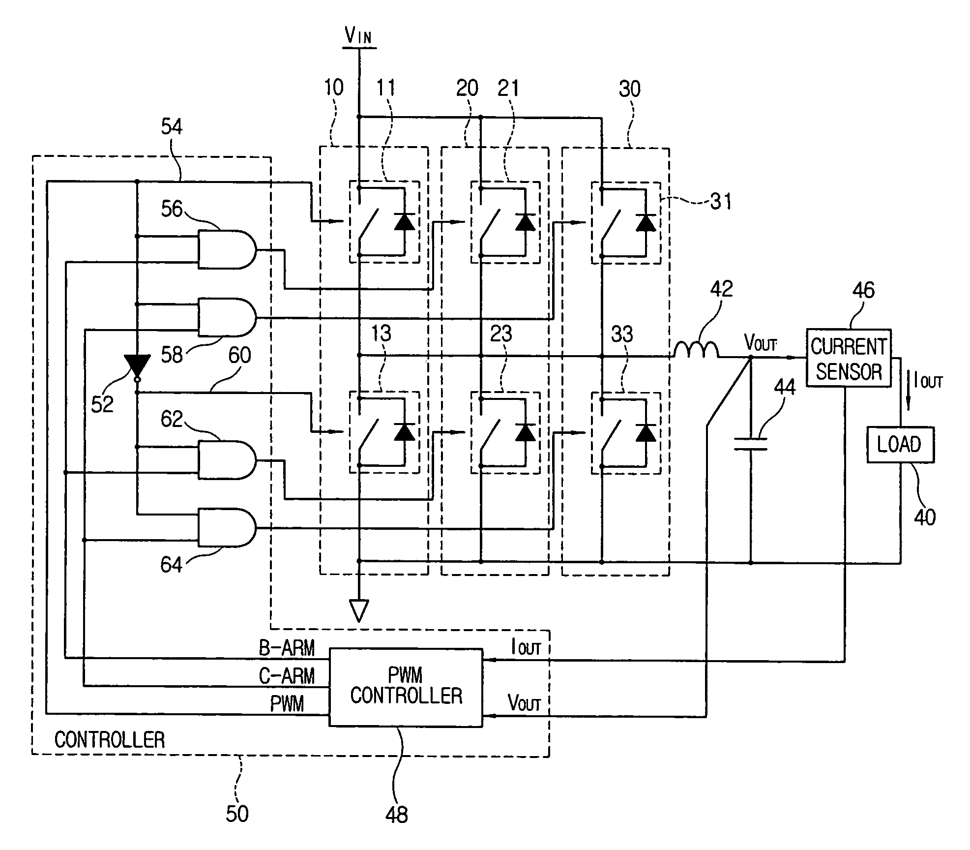
[0033]Referring to FIG. 3, a DC-DC converter according to an embodiment of the present invention comprises a switch part comprising a plurality of switch blocks 10, 20 and 30 (hereinbelow, referred to as “switch arms 10, 20 and 30”) connected in parallel, each switch arm comprising a pair of switches each operated to alternately cut or supply input DC power VIN; an inductor 42 and a capacitor 44 to smooth electric power output by turning on / off of the switch part and supply the smoothen electric power to an electric load 40; a current sensor 46 to sense a load current IOUT flowing through the electric load 40; and a controller 50 to control the switch part to chan...


PUM


Abstract

A DC-DC converter to convert DC power input from an external source into a predetermined DC power required for an electric load. A switch part in which each of a pair of switches that cuts or supplies the input DC power is connected in parallel with at least one other switch. A current sensor senses a load current flowing through the electric load and a controller controls the switch part to enable a number of the switches according to an intensity of the load current sensed by the current sensor. The enabled switches are driven by a PWM signal to cut or supply the input DC power to the load. By changing the number of enabled switches, unnecessary switching is prevented for lower load currents.

Description

CROSS-REFERENCE TO RELATED APPLICATIONS[0001]This application claims the benefit of Korean Patent Application No. 2004-20845, filed Mar. 26, 2004 in the Korean Intellectual Property Office, the disclosure of which is incorporated herein by reference.BACKGROUND OF THE INVENTION[0002]1. Field of the Invention[0003]The present invention relates to a DC-DC converter and a control method thereof, and more particularly, to a DC-DC converter minimizes an unnecessary switching occurring when a light electric load is connected and which improves an efficiency of the DC-DC converter and a control method thereof.[0004]2. Description of the Related Art[0005]Generally, a DC-DC converter converts a DC power input from an external source to a predetermined DC power that an electric load requires. DC-DC converters may be classified into a boost type to raise a voltage of the input DC power and a buck type to drop the voltage of the input DC power.[0006]Hereinbelow, a synchronous buck converter is t...

Claims


Application Information

Patent Timeline
Patent Type & Authority Patents(United States)
IPC IPC(8): G05F1/59H02M3/155G05F1/40H02M3/07H02M3/137H02M3/158
CPCH02M3/1584H02M1/088Y02B70/16H02M2001/0032H03K17/122H02M1/0032Y02B70/10E02D29/12E02D2450/00E02D2600/20
Inventor CHA, JAE-DEOK
Owner SAMSUNG ELECTRONICS CO LTD
Why Eureka
Try Eureka