
Time-multiplexed scanning light source for multi-probe, multi-laser fluorescence detection systems

a scanning light source and multi-laser technology, applied in the field of imaging arts, can solve the problems of reducing the useful wavelength band that may be sensed, speed which does not reach the desired scan rate, and a portion of either stimulated fluorescence signal may significantly overlap the remaining fluorescence signal in terms of wavelength,

Active Publication Date: 2007-10-23
SRI INTERNATIONAL
View PDF37 Cites 10 Cited by
  • Summary
  • Abstract
  • Description
  • Claims
  • Application Information

AI Technical Summary

Benefits of technology

The patent describes an imager that can take pictures of a sample. The sample is placed on a stage and a light path is used to capture the image. The light path has multiple scanning radiation sources that move back and forth to create a beam of light that interacts with the sample. This creates a light signal that is then detected by a photodetector. A processor then processes the detected light signals to create a high-quality image of the sample. The technical effect of this invention is that it allows for faster and more precise imaging of samples, which can be useful in various fields such as biological research and medical diagnosis.

Problems solved by technology

In rare cell studies, a particular problem arises due to the typically low concentration of the rare cells in the blood or other body fluid.
This will, therefore, still result in speeds which do not reach the desired scan rates.
One problem that arises with this arrangement, however, is that a portion of either stimulated fluorescence signal may significantly overlap the remaining fluorescence signal in terms of wavelength.
Selective filtering can reduce this problem but at the cost of reducing the useful wavelength band that may be sensed.
A second problem that arises is that this method would normally make use of a beam splitter or dichroic mirror in the light path of the fluorescent radiation in order to direct desired portions of the fluorescent signal to the respective signal detector, further reducing the intensity of the signal being sensed.

Method used


Image

  • Time-multiplexed scanning light source for multi-probe, multi-laser fluorescence detection systems
  • Time-multiplexed scanning light source for multi-probe, multi-laser fluorescence detection systems
  • Time-multiplexed scanning light source for multi-probe, multi-laser fluorescence detection systems

Examples


Embodiment Construction

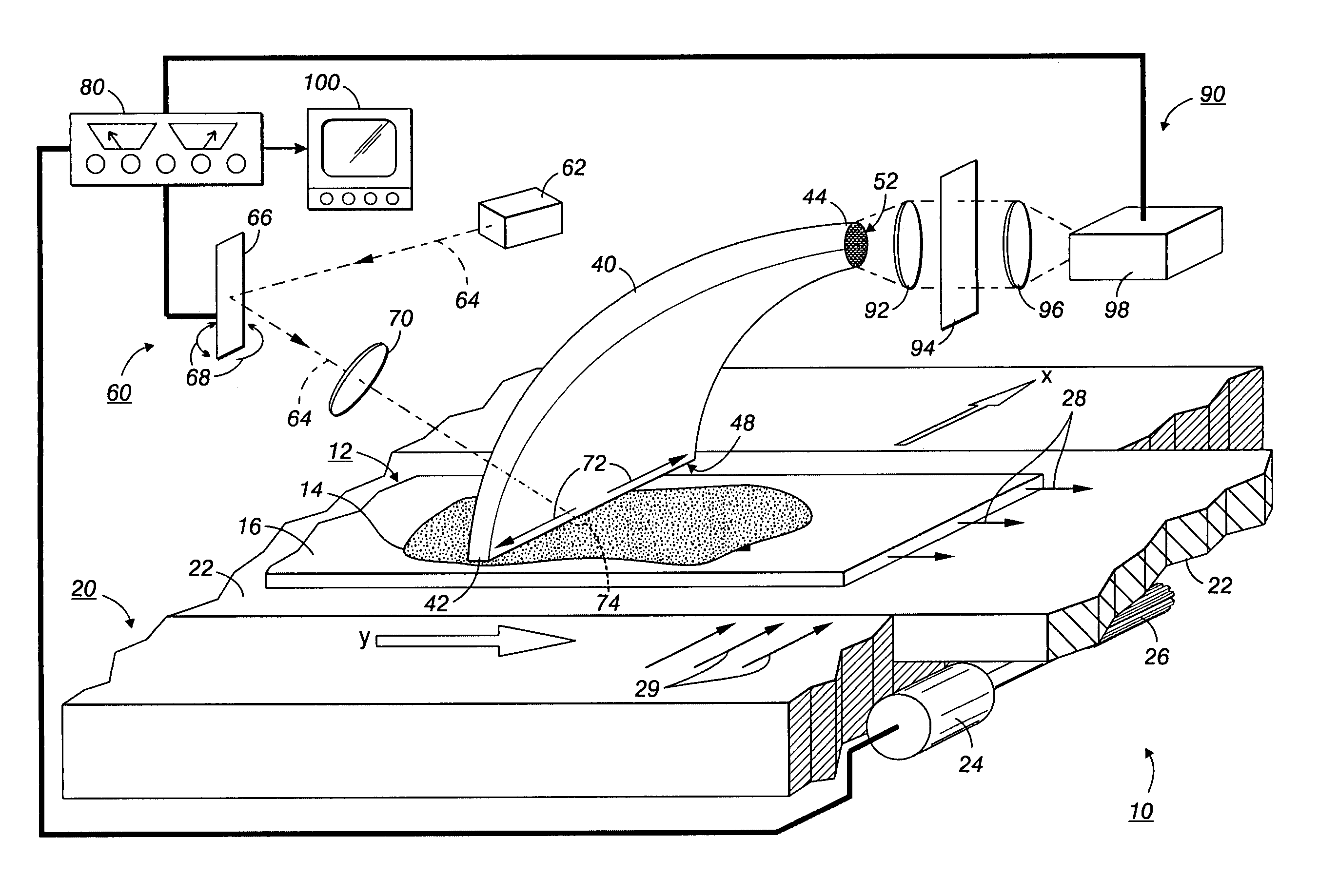
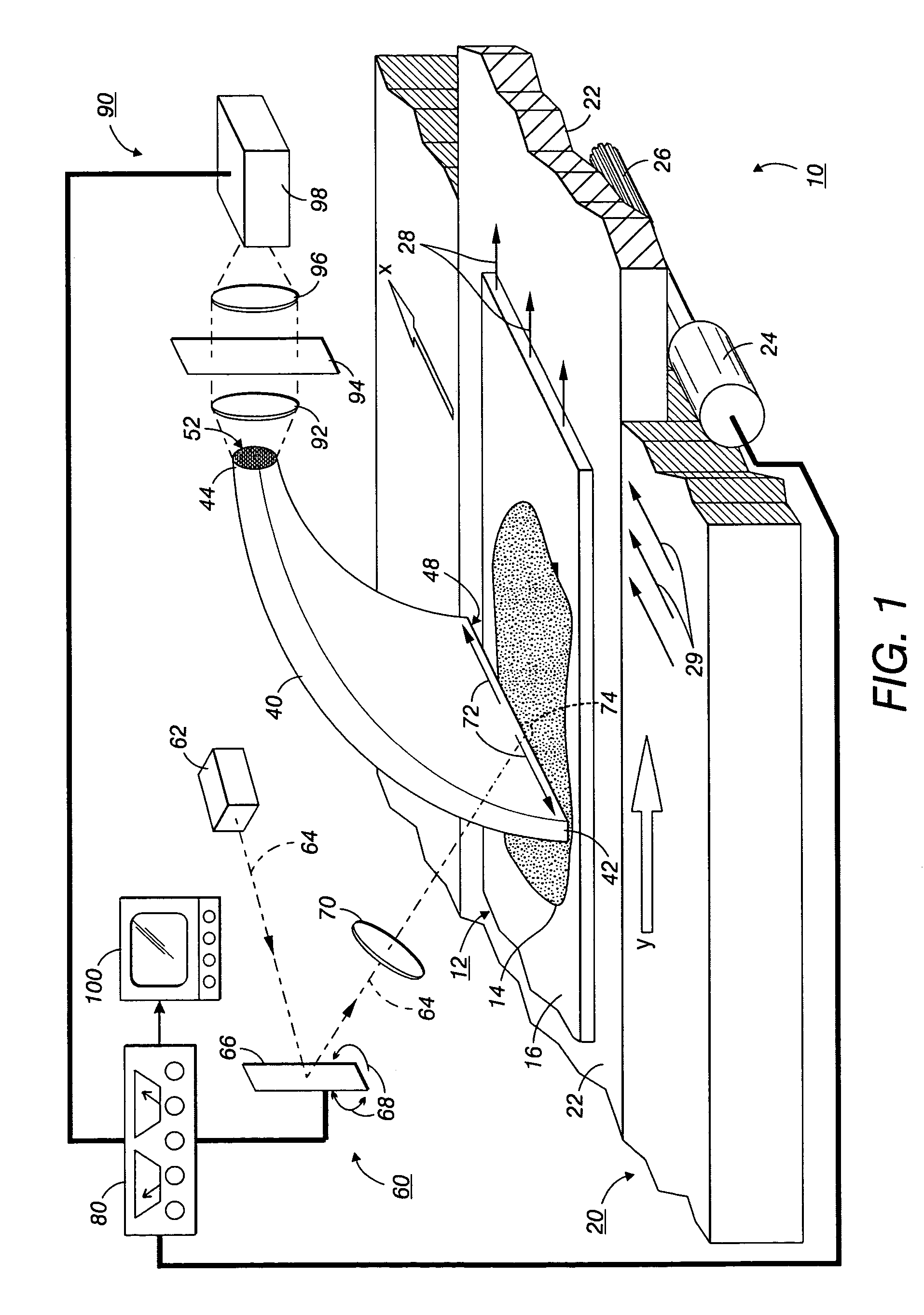
[0020]With reference to FIG. 1, for purposes of understanding the embodiments described herein, an imaging apparatus is first described which utilizes a galvanometer-based laser scanning system with a single laser transmitter and a single detector. Various embodiments are then described which provide an increased scanning speed and which solve the aforementioned problems. In the figure, the imaging apparatus or imager 10 examines a sample 12 such as a biological smear 14 disposed on at least a portion of a surface of a slide 16. Imaging apparatus or imager 10, as expanded upon below, is designed for detection of minute or microscopic material.

[0021]As is known in the art, for cell studies the sample 12 is suitably prepared by drawing a sample of a biological fluid such as, but not limited to, blood or parts of blood from a subject. In a preferred embodiment, the sample is a monolayer of cells. The fluid sample is treated with a fluorescent material, such as but not limited to a mark...


PUM

PropertyMeasurementUnit
areaaaaaaaaaaa
diameteraaaaaaaaaa
diameteraaaaaaaaaa

Abstract

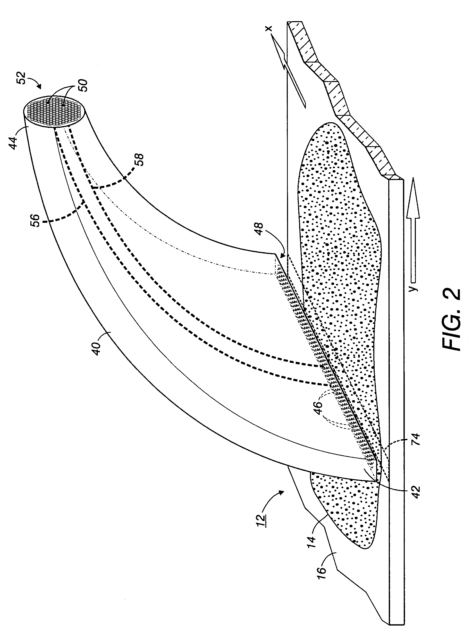
An apparatus images a surface. An imager stage linearly translates the surface in a first direction. A light path has a first end defining an input aperture perpendicular to the first direction and parallel to the surface, and a second end defining an output aperture. A plurality of radiation beams linearly scan and interact in time-multiplexed alternating turns with the surface below the input aperture to produce a time-multiplexed light signal that is collected by the input aperture and transmitted by the light path to the output aperture. A photodetector arrangement detects the light signal at the output aperture. A processor processes the detected time-multiplexed light.

Description

CROSS REFERENCE[0001]The following co-pending application U.S. Ser. No. 10 / 616,366, Filed Jul. 9, 2003, is hereby incorporated by reference in its entirety.BACKGROUND[0002]The present exemplary embodiments relate to the imaging arts, and find particular application in conjunction with low and high-density cell detection, locating, and identifying in blood smears, biological assays, and the like across distinct imaging systems, and will be described with particular reference thereto. However, it is to be appreciated the exemplary embodiments will also find application in imaging, locating and identifying other types of low- or high-density features on various substantially planar surfaces and samples, such as imaging semiconductor wafers, imaging particulate contaminants in fluids or thin solid films, and so forth, with such imaging finding specific uses in the printing arts, electronic arts, medical arts, and other scientific and engineering areas.[0003]In rare cell studies, a parti...

Claims


Application Information

Patent Timeline
Patent Type & Authority Patents(United States)
IPC IPC(8): G01N21/64G01J3/24G01N21/25A61B5/00G01N21/76
CPCG01N15/1468G01N21/6456G01N2201/1085
Inventor CURRY, DOUGLAS N.BRUCE, RICHARD H.
Owner SRI INTERNATIONAL
Learn More