Stratum disposal monitoring system

a monitoring system and stratum technology, applied in the field of stratum disposal monitoring system, can solve the problems of increasing cost, insufficient durability of monitoring equipment, and the monitoring method not keeping up with monitoring

Inactive Publication Date: 2007-10-30
KAJIMA CORP
View PDF25 Cites 24 Cited by
  • Summary
  • Abstract
  • Description
  • Claims
  • Application Information

AI Technical Summary

Benefits of technology

[0056]In addition, transmission of the data via the relay with the radio system of electromagnetic or sound wave type or the like ensures that the measured data is securely transmitted even through the underground part after closure of the disposal field. Further, the monitoring device and the relay are of a structure that is good for a long-term service and withstands corrosion, degradation and the like over a long period of time under the underground high-temperature / high-pressure environment, with the result that long-term monitoring of the behavior of the wastes and their surroundings is executable securely.

Problems solved by technology

However, the above conventional monitoring method has the disadvantages of requiring a large number of sensors, drilled holes and communication cables, and taking much time for installation works and maintenance, resulting in an increase in cost.
Or, in certain circumstances, maintenance is not executable, so that the above conventional monitoring method fails to keep up with monitoring.
However, as described in a later instance, the durability of the monitoring equipment is considered to be not so sufficient for the long-term service, so that the conventional monitoring method has the disadvantage of finding difficulty in exchanging once-embedded sensors and cables with new ones.
In addition, it is reported that the computerized execution of typical civil engineering works frequently causes some failures in about 30% of the sum total of sensors until the works covering a period of several years are completed.
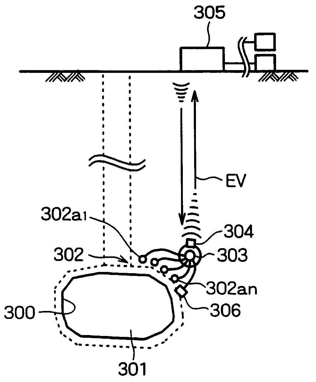
However, the above conventional communication cable system has the following problems.(1) It is feared that the cable having been laid underground within the access gallery leads to the water passage, and further to the selective migration route of nuclides in future.(2) The underground cable existing under the underground high-temperature / high-pressure environment is limited in durability, and also covers the range of a long distance, so that degradation, disconnection and the like of the cable result in long-term monitoring of difficulty.(3) The underground sensor existing under the underground high-temperature / high-pressure environment is limited in durability, resulting in long-term monitoring of difficulty as well.
However, the above monitoring system with the elastic waves has the following problems.
(1) It is difficult to propagate the elastic waves from the deep underground part at a depth in the range of several hundred to several tens of hundred meters from the ground without causing attenuation.
(3) Each sensor 302a is existent in the high-temperature / high-pressure underground part, resulting in long-term monitoring of difficulty.

Method used


Image

  • Stratum disposal monitoring system
  • Stratum disposal monitoring system
  • Stratum disposal monitoring system

Examples


Embodiment Construction

[0110]The present invention will now be described with reference to illustrated embodiments. The illustrated embodiments are applications of the present invention to a stratum disposal field for high-level radioactive wastes. FIGS. 1 to 38 respectively show an embodiment of a gallery monitoring method with a running path and a movable monitoring device of the present invention.

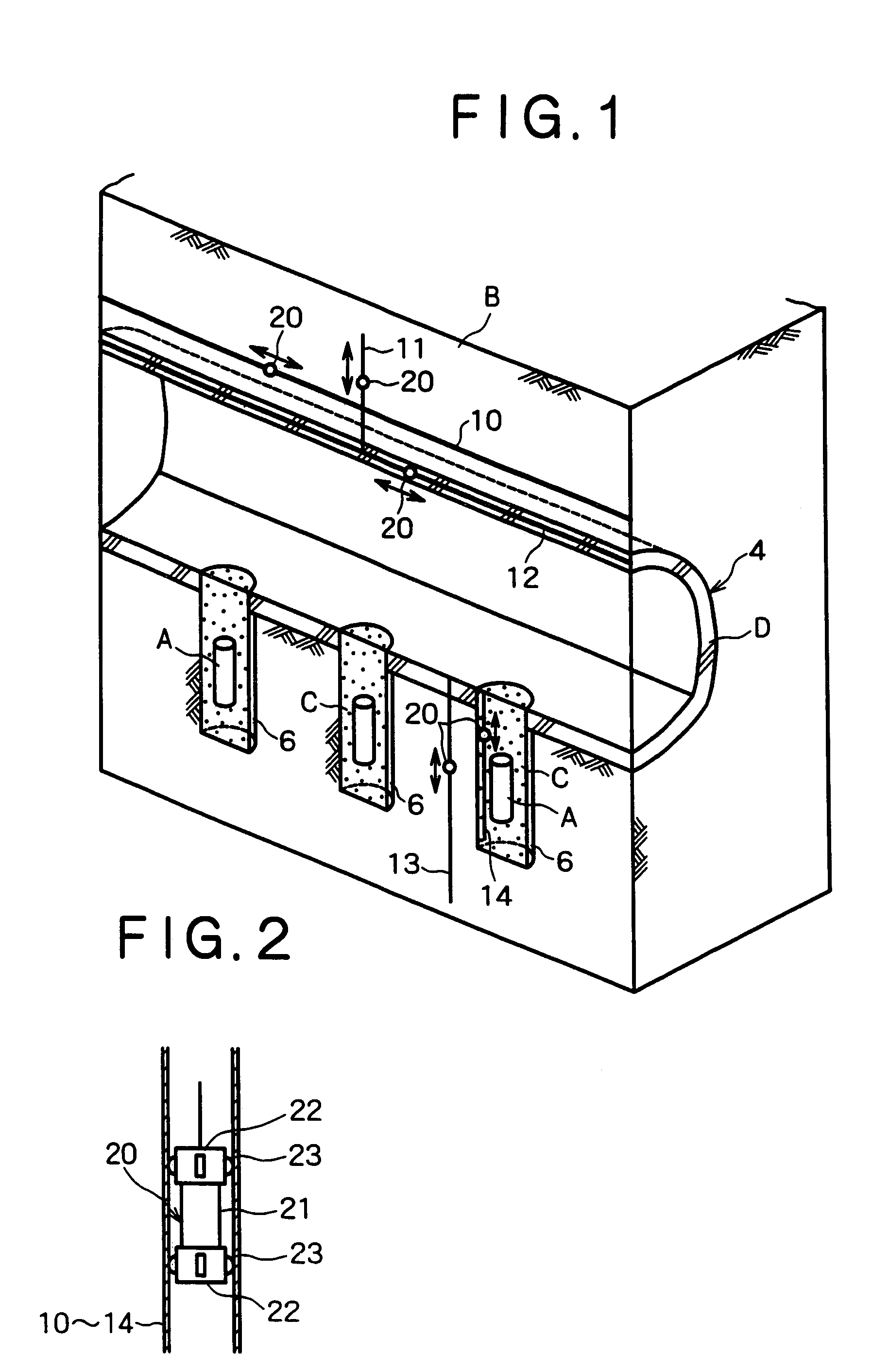
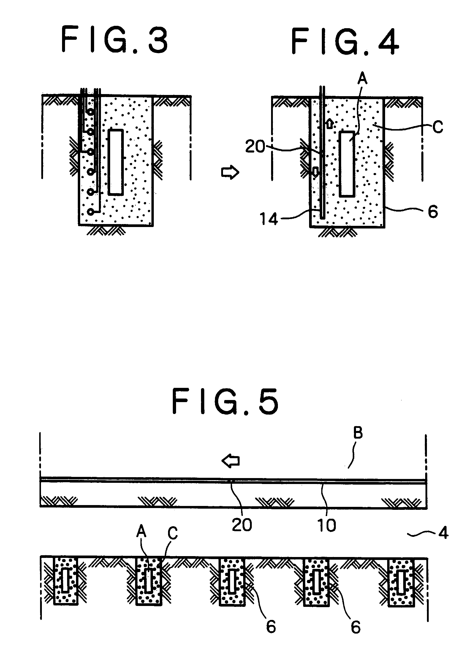
[0111]In FIGS. 1 and 2, there is shown an application of the above gallery monitoring method to the layout of the vertical disposal-hole pattern as shown in FIGS. 46 to 49. A running tube 10, parallel to an axial direction of a disposal gallery 4, is installed in a rock bed B in the vicinity of the gallery 4. A running tube 11 is also installed in the rock bed B in the vicinity of the gallery 4 at a right angle to the axial direction of the gallery 4. In addition, a running tube 12, parallel to the axial direction of the disposal gallery 4, is installed within or on a support (such as sprayed concrete and seco...


PUM


Abstract

In monitoring a stratum disposal field for wastes, running tubes installed in the vicinity of a gallery or disposal holes, in a nearby rock bed, or within a gallery support or buffer members in the disposal holes have installed therein a movable monitoring device provided with various sensors, a water sampling device and the like. The monitoring device may be movable or fixed in a predetermined position, for measurement of the temperature, displacement, strain, stress and underground water in connection with the rock bed, the gallery support or the disposal space buffer members. Measurement of the clearances in the rock bed, the gallery support back or the disposal space buffer members is monitored. Also, sampling of underground water in the rock bed, the gallery support or the buffer members is effected, thus reducing the number of sensors, drilled holes, communication cables to facilitate the exchange or maintenance of the sensors, communication cables and the like. Further, the data measured by the monitoring device embedded in the buffer member or the like is transmitted by radio to a movable data collecting device in the running tube, or the data measured by the monitoring device is transmitted by radio to a management device disposed on the ground or somewhere else via a relay.

Description

TECHNICAL FIELD[0001]This invention relates to a gallery monitoring method, and more particularly, to monitoring as in a stratum disposal field for underground disposal of radioactive wastes and the like. The present invention also relates to a monitoring system for stratum disposal wastes and the like, and more particularly, is effectively applied to long-term monitoring and management of high-level radioactive wastes subjected to underground disposal in a deep underground part.BACKGROUND ART[0002]A variety of approaches to stratum disposal of radioactive wastes have been heretofore proposed. For instance, stratum disposal of high-level radioactive wastes has been projected with a system, which conducts stabilizing treatment of the wastes into vitrified wastes by melting the wastes together with a glass material at high temperatures to pour into a stainless steel canister, and stores the vitrified wastes tightly in a thick steel-plate airtight container called an over-pack to effec...

Claims


Application Information

Patent Timeline
Patent Type & Authority Patents(United States)
IPC IPC(8): G21F9/34B09B1/00E02D19/00G21C17/00
CPCB09B1/00G21F9/34G21C17/00E02D19/00Y02E30/30
Inventor OKUTSU, KAZUOTAKAMURA, HISASHI
Owner KAJIMA CORP
Why Eureka
Try Eureka