
Chemical reactor and method for gas phase reactant catalytic reactions

a reaction reaction and reaction method technology, applied in the direction of machines/engines, metal/metal-oxide/metal-hydroxide catalysts, and chemical production of bulk chemicals, can solve the problems of large equipment volume, aluminum application, and large usable surface area of microchannel walls, etc., to achieve short contact time, reduce contact time, and good yield

Inactive Publication Date: 2007-10-30
BATTELLE MEMORIAL INST
View PDF37 Cites 37 Cited by
  • Summary
  • Abstract
  • Description
  • Claims
  • Application Information

AI Technical Summary

Benefits of technology

[0051]Another advantage of the present invention is that good yields can be obtained with short contact times. In preferred methods, the contact time is less than 100 milliseconds (ms), more preferably less than 50 ms and still more preferably between 1 and 25 ms. Contact time may be reduced by reducing the diffusion distance between the bulk flow and the porous catalyst while concurrently reducing channel length. At these contact times, in a preferred embodiment of hydrocarbon steam reforming, at least 70%, more preferably at least 90%, of the equilibrium conversion of the hydrocarbon entering the beginning of said at least one reaction chamber is converted to hydrogen, carbon monoxide and / or carbon dioxide. Similar improvements can be obtained in other processes.
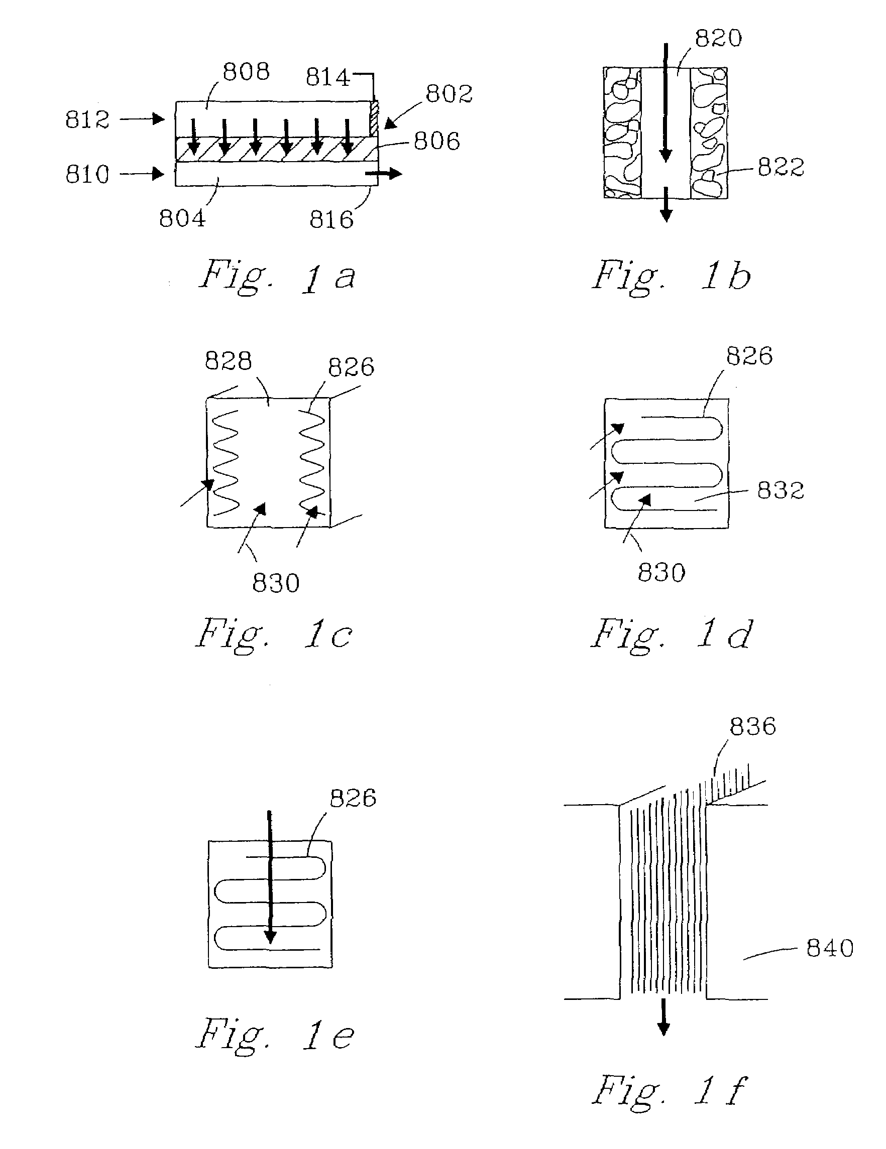
[0052]FIG. 1a illustrates a reaction chamber 802 having a first compartment 804 having at least one dimension of about 2 mm or less, a porous catalyst material 806 and a second compartment 808. This reaction chamber can be used in several ways. For example, a catalyzed reaction can be carefully controlled by passing one reactant (e.g., methane) 810 into the first compartment, passing a second reactant (e.g., water) 812 into the second compartment and, in this manner, effecting a controlled reaction within the porous catalyst material 806. Flow can be controlled by pressure differentials or by plugging one compartment (e.g. plug 814), and the product(s) formed in the porous material can be directed through outlet 816.
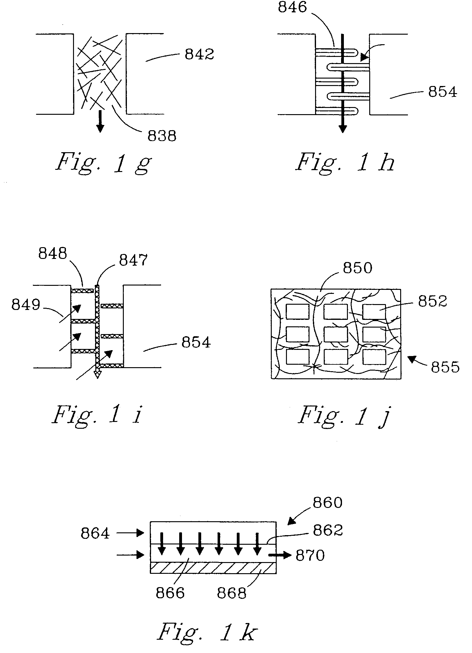
[0053]FIG. 1k illustrates apparatus 860 where a flow distribution layer 862 (typically a sheet having random, regular, or spaced pores, slots, holes, or the like) can distribute feed 864 along a length of the reaction chamber 866. The reaction chamber 866 preferably contains a porous catalyst material 868 (although illustrated as a single layer along the length of the reaction chamber—thus enabling low pressure drop, it should be recognized that a porous catalyst material could have any of the configurations described herein). Product 870 exits the reaction chamber. Distributing the feed serves to lower the local partial pressure of one of the reactants. This has advantages for reactions that are parallel or series-parallel in nature, where the local concentration tends to favor one reaction pathway over another. For example, partial oxidation reactions can be improved by this distributed feed approach which increases selectivity to the desired product over the undesired deep oxidation products.
[0054]FIG. 1b illustrates an embodiment of the inventive reaction chamber in which a bulk flow path 820 is disposed between porous catalyst material 822, although some flow may convectively travel through the large pores in the porous catalyst material. Flow through the large pores increases when the pore diameter of the porous insert increases and approaches an order of magnitude below the hydraulic diameter of the open area. This reaction chamber could be configured as a tube, with a ring or partial ring of catalyst, but is more preferably a planar arrangement. The planar arrangement enables economical stacking of reaction chambers with other components such as: additional reaction chambers, heat exchangers, etc. The contiguous, straight-through configuration of the bulk flow channel creates the opportunity to perform gas phase catalysis with low pressure drops.
[0055]FIGS. 1c and 1d illustrate reaction chamber configurations in which corrugated catalyst inserts 826 provide high surface area for gas phase catalysis while contiguous flow paths 828, 832 enable catalysis to be performed with low pressure drops. The inserts 826 either have a surface coating of a porous catalyst material or, preferably, are comprised of a porous catalyst material. A similar configuration is illustrated in FIG. 2d.
[0056]FIG. 1e illustrates an embodiment in which a corrugated porous catalyst material 826 is disposed in the reaction chamber such that gas flow is partially through, and around the catalyst. This configuration ensures contact with the porous catalyst; however, this configuration has the disadvantage of significantly higher pressure drops but the advantage of more intimate contact of the reactants with the active catalyst surface.

Problems solved by technology

However, equipment, specifically reactor volume is generally large because of mass and heat transfer limitations.
This approach has the disadvantage that the only usable surface area is that of the microchannel wall.
Disadvantages of this approach include that it is only applicable for aluminum, and limited surface area.
A disadvantage was a tendency to create relatively large pressure drops by forcing the fluid to flow through the packed microbed.
Again, a disadvantage was large pressure drop through the metal foam.

Method used


Image

  • Chemical reactor and method for gas phase reactant catalytic reactions
  • Chemical reactor and method for gas phase reactant catalytic reactions
  • Chemical reactor and method for gas phase reactant catalytic reactions

Examples


example 1

[0072]An experiment was conducted to demonstrate the present invention using 1 microchannel for methane steam reforming. The microchannel was placed within a tube furnace to provide the required endothermic reaction heat. The microchannel was 1.52-cm long and 0.66-cm high. The width (or opening) of the microchannel was 0.0762-cm or 762-microns. The 0.0762-cm width included two porous structures that covered opposite walls and each had a width of 254-microns leaving a bulk flow path between the two porous structures of 254 microns. The porous structure contained a catalyst of 13.8%—Rh / 6%—MgO / Al2O3 on a metal felt of FeCrAl alloy obtained from Technetics, Deland, Fla. 13.8 wt % Rh6 wt % MgO / Al2O3 powdered catalyst was prepared by 1) calcining a high surface area gamma-alumina at 500° C. for 5 hours; 2) impregnating the gamma alumina with MgO using the incipient wetness method with an aqueous solution of magnesium nitrate; and obtaining an MgO modified gamma alumina support; 3) drying ...

example 2

[0076]An experiment was conducted utilizing apparatus illustrated in FIG. 7a including a fuel combustor 700, water vaporizer 702, a reactant preheat heat exchanger 704, and a steam-reforming unit 706. The steam reforming unit 706 was constructed with 12 parallel channels (FIG. 7b) 1, 2, 3 . . . 12 each of length 2.79 cm, height 2.54 cm, and width of 750 microns. The porous structure 106 was felt FeCrAl alloy with a porosity ranging from 35% to 90% obtained from Technetics, Orlando, Fla., having a width of about 250 micron. Pieces of metal felt with length and height nearly equal to the channel length and height were coated with the catalyst using the same slurry dipping method and powder catalyst as described in Example 1. These felts were affixed to the walls on opposite sides of the channels leaving a bulk flow path of about 250 microns in each channel. The reactor microchannels were interspersed with heat exchange channels a, b, c . . . m to provide the endothermic reaction heat....

example 3

[0079]Steam reforming experiments were conducted to evaluate the effectiveness of various catalyst configurations within a reaction chamber. Engineered catalysts with various structures were synthesized and activated using the same procedures—as described in Example 1. The felt and ruffle substrates are porous materials formed from FeCrAl alloy fibers, and were purchased from Technetics, Deland, Fla.

[0080]Catalyst was inserted within the single channel device with a snug fit. All catalysts were evaluated in a single channel device. The single channel device is placed in a tube furnace. Reactants were preheated in the top zone of the furnace, and were introduced into the single channel device in a down-flow mode. Steam reforming of methane was conducted at a fixed contact time, a steam-to-carbon ratio of 2 / 1, and a temperature maintained at 850° C. (chamber temperature was continuously monitored by a thermocouple). Effluent flowrate was measured by a bubble flowmeter, and product was...


PUM

PropertyMeasurementUnit
widthaaaaaaaaaa
heightaaaaaaaaaa
sizesaaaaaaaaaa

Abstract

The present invention provides chemical reactors and reaction chambers and methods for conducting catalytic chemical reactions having gas phase reactants. In preferred embodiments, these reaction chambers and methods include at least one porous catalyst material that has pore sizes large enough to permit molecular diffusion within the porous catalyst material.

Description

RELATED APPLICATIONS[0001]This application is a divisional of U.S. patent application Ser. No. 09 / 640,903, filed Aug. 16, 2000, now U.S. Pat. No. 6,680,044, which was a Continuation-In-Part of U.S. patent application Ser. No. 09 / 375,614, filed Aug. 17, 1999, now U.S. Pat. No. 6,488,838, both of which are incorporated herein in full, as if reproduced below.FIELD OF THE INVENTION[0002]The present invention is a chemical reactor and method for gas phase reactant catalytic reactions.[0003]As used herein, the term “molecular diffusion” is used in its classic sense of the transfer of mass based upon Brownian motion between adjacent layers of fluid in laminar, transition, or turbulent flow, and includes transfer of mass between adjacent layers of fluid that are stagnant.[0004]As used herein, the term “Knudsen diffusion” means Knudsen flow, or free molecule flow, wherein the mean free path of the molecules is long compared to a characteristic dimension of the flow field, for example the por...

Claims


Application Information

Patent Timeline
Patent Type & Authority Patents(United States)
IPC IPC(8): B01J8/04B01D50/00B01D53/22B01D71/02B01J12/00B01J19/00B01J19/24B01J23/60B01J37/02B01J37/03C01B3/38C01B3/48C01B3/50C01B3/56C01B13/02H01M8/06
CPCB01J12/007B01J23/60B01J37/0215C01B3/38C01B3/501C01B13/0251H01M8/0612B01J19/0093Y02E60/50B01J37/031B01J2219/00835B01J2219/2453B01J2219/2465B01J2219/2474B01J2219/2475B01J2219/2479B01J2219/2482B01J2219/2497C01B2203/0233C01B2203/0283C01B2203/0405C01B2203/041C01B2203/044C01B2203/047C01B2203/065C01B2203/066C01B2203/0811C01B2203/0833C01B2203/1005C01B2203/1011C01B2203/1029C01B2203/1035C01B2203/1041C01B2203/1052C01B2203/1064C01B2203/1076C01B2203/1082C01B2203/1094C01B2203/1217C01B2203/1223C01B2203/1241C01B2203/1276C01B2203/1288C01B2203/148C01B2203/1604C01B2203/1619C01B2203/1652C01B2203/1676C01B2210/0046Y02P20/52B01J19/00
Inventor TONKOVICH, ANNA LEE Y.WANG, YONGFITZGERALD, SEAN P.MARCO, JENNIFER L.ROBERTS, GARY L.VANDERWIEL, DAVID P.WEGENG, ROBERT S.
Owner BATTELLE MEMORIAL INST
Learn More