Wafer stage operable in a vacuum environment

a vacuum environment and stage technology, applied in the field of stage assembly, can solve the problems of inaccurate spherical detection, inaccurate spherical detection, and inability to accurately detect the product, etc., and achieve the effect of accurate spherical detection

Inactive Publication Date: 2007-10-30
NIKON CORP
View PDF9 Cites 19 Cited by
  • Summary
  • Abstract
  • Description
  • Claims
  • Application Information

AI Technical Summary

Benefits of technology

[0015]A stage apparatus which includes vacuum-compatible bearings, e.g., vacuum-compatible air bearings, enables the stage apparatus to be used in a vacuum environment without a significant risk of the vacuum environment being contaminated due to leakage from the air bearings. The use of a substantially levitating fine stage as a part of such a stage apparatus further enables an object such as a wafer to be accurately scanned.

Problems solved by technology

When the performance of a precision instrument is adversely affected, as for example by contamination, products formed using the precision instrument may be improperly formed and, hence, function improperly.
For example, if a photolithography machine which is not designed to operate in a vacuum is used in a vacuum environment, the photolithography machine may cause the vacuum environment to be contaminated.
As a result, the vacuum level associated with the environment may be compromised, thereby affecting an overall photolithography process which utilizes the photolithography machine.
In general, an EUV lithography system must operate in a relatively high vacuum environment, which may be expensive to maintain, as any gas leakage into the vacuum environment must be corrected in order to prevent the vacuum level from being significantly compromised.
Maintaining the vacuum level in a vacuum environment such as a chamber to compensate for gas leakage and other contamination is often difficult or impractical.
Opening and closing, i.e., unsealing and resealing, the vacuum chamber is often a tedious process.
The accessing of motors within a vacuum chamber exposes the vacuum chamber to contaminants and moisture, which may contaminate the surfaces of components within the vacuum chamber.
Within a vacuum chamber, it is difficult to maintain an acceptable operational temperature, as motors used to move scanning stages, as for example fine scanning stages, often heat up during operation.
When the temperature within the vacuum chamber is too high, the operation of sensors within the vacuum chamber may be compromised.
Since there is no air available in the vacuum chamber during an EUV lithography process, the only cooling that is available within the vacuum chamber results from conduction and radiation.
As such, maintaining an acceptable temperature within the vacuum chamber is often a difficult process.

Method used


Image

  • Wafer stage operable in a vacuum environment
  • Wafer stage operable in a vacuum environment
  • Wafer stage operable in a vacuum environment

Examples


Embodiment Construction

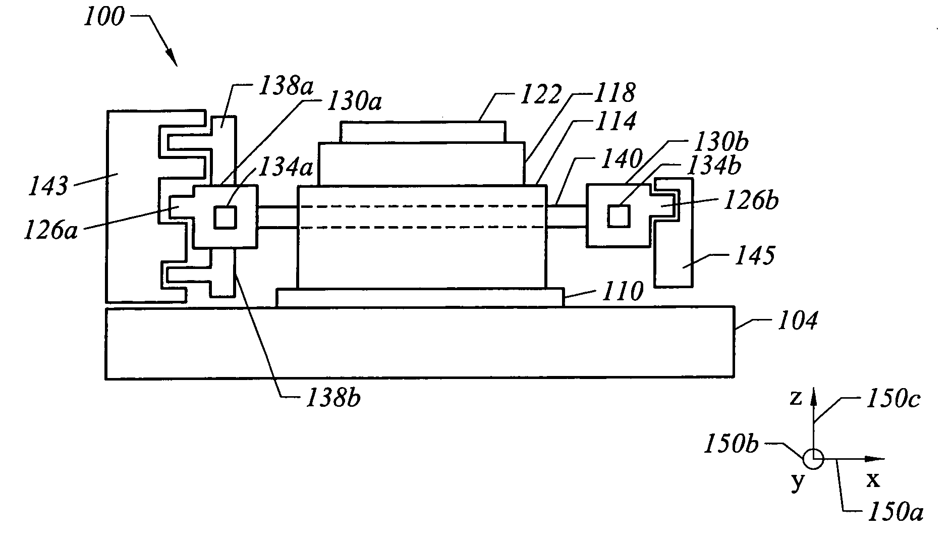
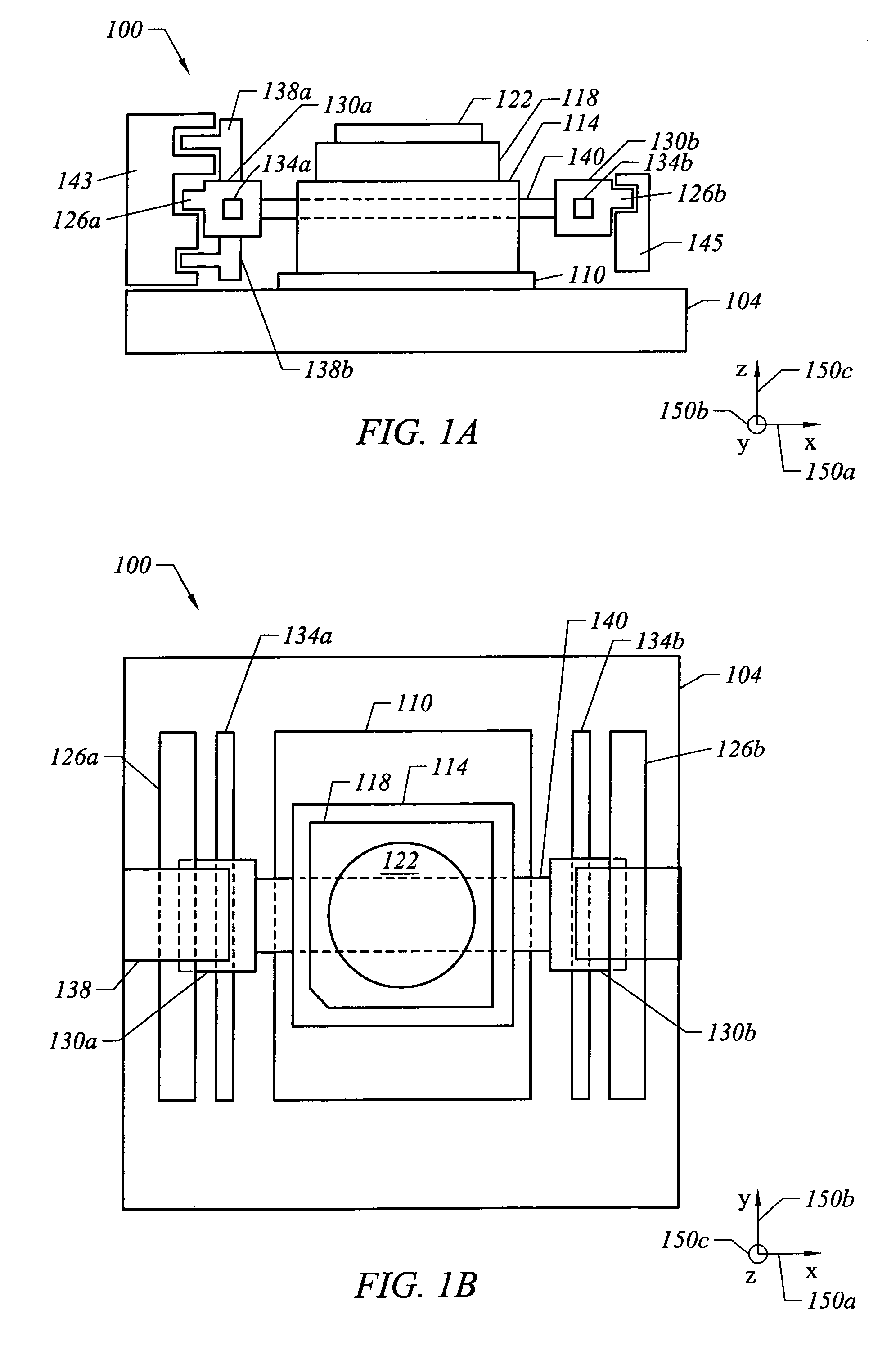
[0033]The performance of extreme ultraviolet (EUV) lithography system is often compromised when an acceptable vacuum level or an acceptable temperature within a vacuum chamber may not be maintained. Hence, the ability to efficiently and relatively easily maintain a desired vacuum level and to maintain a desired temperature in a vacuum environment associated with an EUV lithography system is critical.

[0034]A stage arrangement which is arranged to be used in a vacuum system may include vacuum-compatible air bearings which generally leak a relatively insignificant amount of gas, a guideless coarse stage assembly, and a substantially levitating fine stage assembly. The use of vacuum-compatible air bearings generally reduces the likelihood that a vacuum system is contaminated, as air or pressurized air is less likely to leak from such air bearings into the surrounding vacuum environment. In one embodiment, substantially all air bearings in the stage arrangement are vacuum-compatible. The...


PUM

PropertyMeasurementUnit
wavelengthsaaaaaaaaaa
velocityaaaaaaaaaa
wavelengthaaaaaaaaaa

Abstract

Methods and apparatus for enabling a stage apparatus to scan an object within a vacuum environment associated with an extreme ultraviolet lithography system are disclosed. According to one aspect of the present invention, a stage apparatus that is suitable for operation in a vacuum environment includes a coarse stage assembly that include a coarse stage and at least one air bearing that is vacuum-compatible. The stage apparatus also includes a fine stage assembly which has a fine stage that is arranged substantially adjacent to the coarse stage. The fine stage is arranged to be positioned relative to the coarse stage using electromagnetic energy.

Description

BACKGROUND OF THE INVENTION[0001]1. Field of Invention[0002]The present invention relates generally to semiconductor processing equipment. More particularly, the present invention relates to a stage assembly which is suitable for use in a vacuum environment such as a vacuum environment associated with an extreme ultraviolet lithography system.[0003]2. Description of the Related Art[0004]For precision instruments such as photolithography machines which are used in semiconductor processing, factors which affect the performance, e.g., accuracy, of the precision instrument generally must be dealt with and, insofar as possible, eliminated. When the performance of a precision instrument is adversely affected, as for example by contamination, products formed using the precision instrument may be improperly formed and, hence, function improperly. For example, if a photolithography machine which is not designed to operate in a vacuum is used in a vacuum environment, the photolithography mach...

Claims


Application Information

Patent Timeline
Patent Type & Authority Patents(United States)
IPC IPC(8): H02K41/00G03B27/58G03F7/20G21K5/10H01J37/20H02K7/09
CPCG03F7/70716H01J37/20G03F7/70841G03F7/70816
Inventor HAZELTON, ANDREW J.
Owner NIKON CORP
Why Eureka
Try Eureka