
Air bearing slider with three-projection trailing center pad

a slider and center pad technology, applied in the field of information storage devices, can solve the problems of unrealized devices, and undesirable changes in flying height, and achieve the effect of reducing the ambient pressure of the atmospher

Inactive Publication Date: 2007-10-30
WESTERN DIGITAL TECH INC
View PDF17 Cites 46 Cited by
  • Summary
  • Abstract
  • Description
  • Claims
  • Application Information

AI Technical Summary

Problems solved by technology

Optimally the flying height would remain constant at a desired value, but that is not achieved in practical devices.
Manufacturing variations changes in the operating environment, or changes in the position of the air bearing surface of the slider tend to cause undesirable changes in flying height.
One environmental factor that can cause an undesirable change in flying height is the ambient pressure of the atmosphere.
An example of a manufacturing variation that can cause an undesirable change in flying height is the longitudinal out-of-plane curvature of the air bearing surface, commonly known as the “crown” of the air bearing surface.
Another example of a manufacturing variation that can cause an undesirable change in flying height is the pre-load force (also known as “gram load”) that presses the air bearing slider against the spinning disk surface during operation.
An undesirable change in flying height can also result from a change in the linear velocity of the disk surface that is experienced by the air bearing slider during operation.
The miniaturization that is characteristic of micro-drives exacerbates several of the challenges to air bearing design.
The resulting reduction in slider length challenges air bearing designers to give the air bearing adequate pitch stiffness to resist applied pitch torques.
The resulting reduction in air bearing width challenges air bearing designers to give the air bearing adequate roll stiffness to resist applied roll torques.
Ramp load / unload presents additional challenges to the air bearing designer.

Method used


Image

  • Air bearing slider with three-projection trailing center pad
  • Air bearing slider with three-projection trailing center pad
  • Air bearing slider with three-projection trailing center pad

Examples


Embodiment Construction

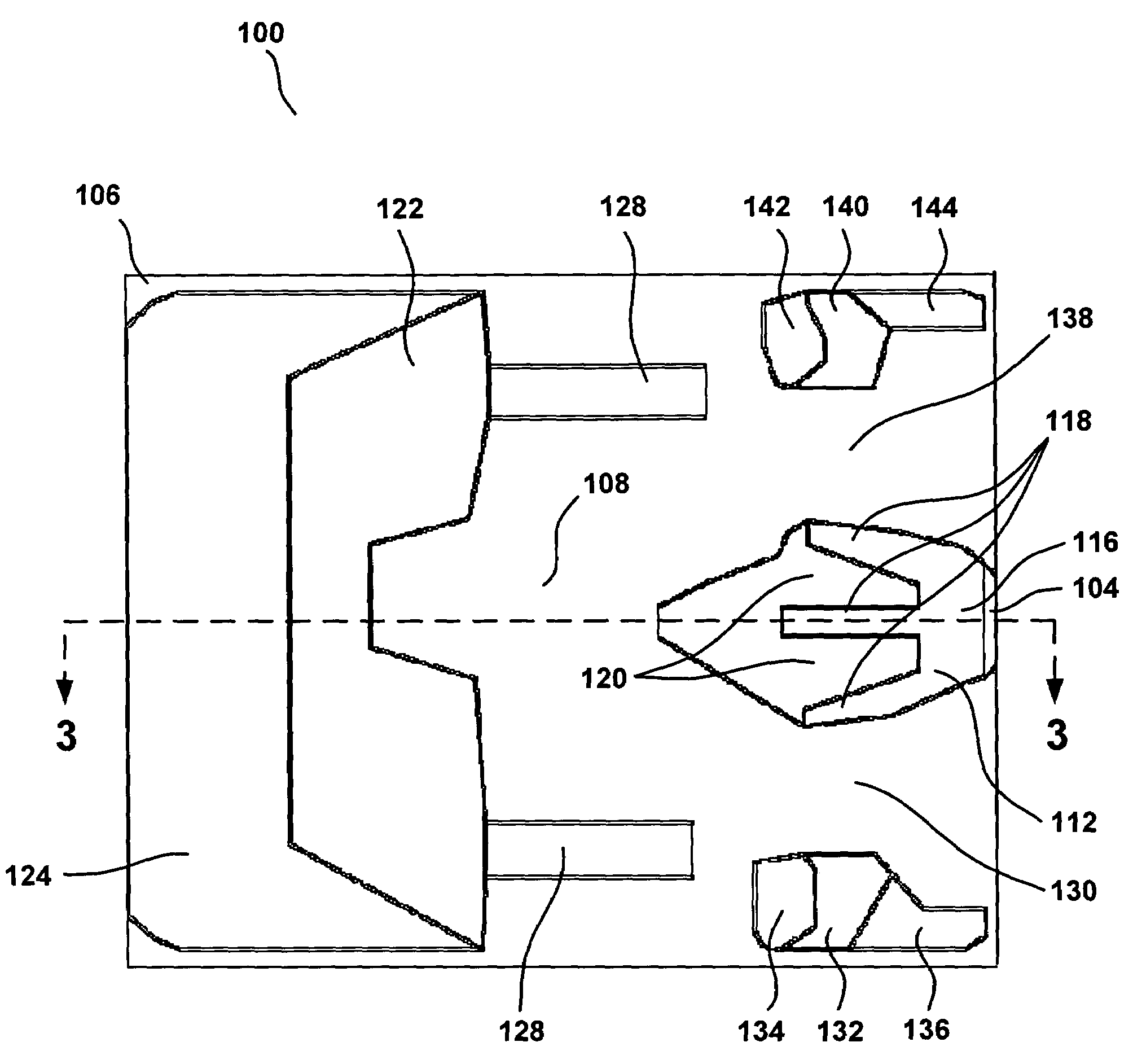
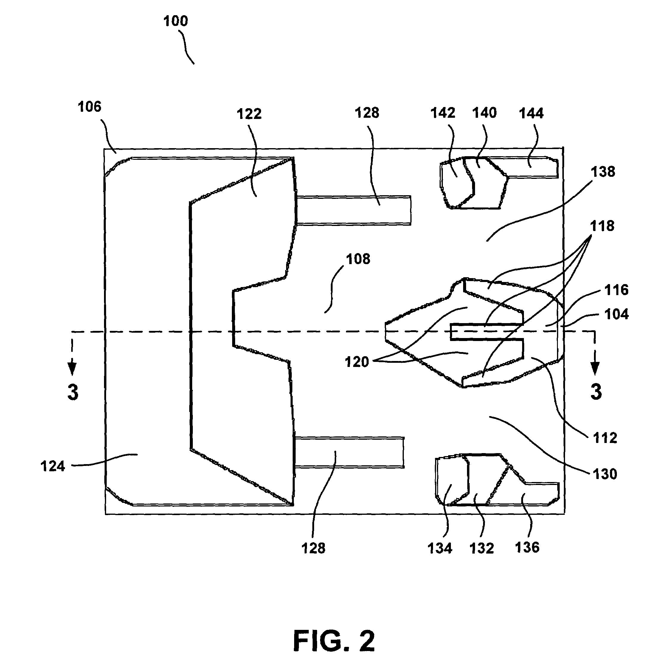
[0021]Now referring to the exemplary embodiment shown in FIG. 2 and FIG. 3, head 100 comprises a transducer 104 for at least reading information from the disk. In certain embodiments, the transducer 104 is a merged thin film magnetic transducer comprising an inductive writer and magneto resistive read element. In such embodiments, the magneto resistive element may be a giant magneto resistive element (GMR) or tunneling magneto resistive element (TMR). In such embodiments, the writer may be a perpendicular magnetic recording (PMR) writer.

[0022]Head 100 also comprises a slider 102, which is typically fabricated from a ceramic material such as alumina titanium carbide. Slider 102 includes an air bearing surface 106, which may be formed on the surface of slider 102 by etching or ion milling and has a geometry that may be defined by use of a mask.

[0023]In the embodiment of FIG. 2 and FIG. 3, the air bearing surface 106 includes a central cavity 108 having a bottom surface 110. During ope...


PUM


Abstract

A novel air bearing can be used in a magnetic hard disk drive or other information storage device. The novel air bearing includes a central cavity having a bottom surface, a leading pad adjacent to the central cavity, a trailing center pad having a top surface, and two inter-projection step regions. The trailing center pad has an aft region adjacent to the transducer and three projections extending from the aft region towards the central cavity. The central cavity separates the three projections from the leading pad. Each of the two inter-projection step regions lies at least partially between the projections, and each includes a surface at an intermediate level between a level of the top surface and the level of the bottom surface. The novel air bearing may be adequately insensitive to one or more factors affecting flying height variation in a micro-drive utilizing ramp load / unload of the slider.

Description

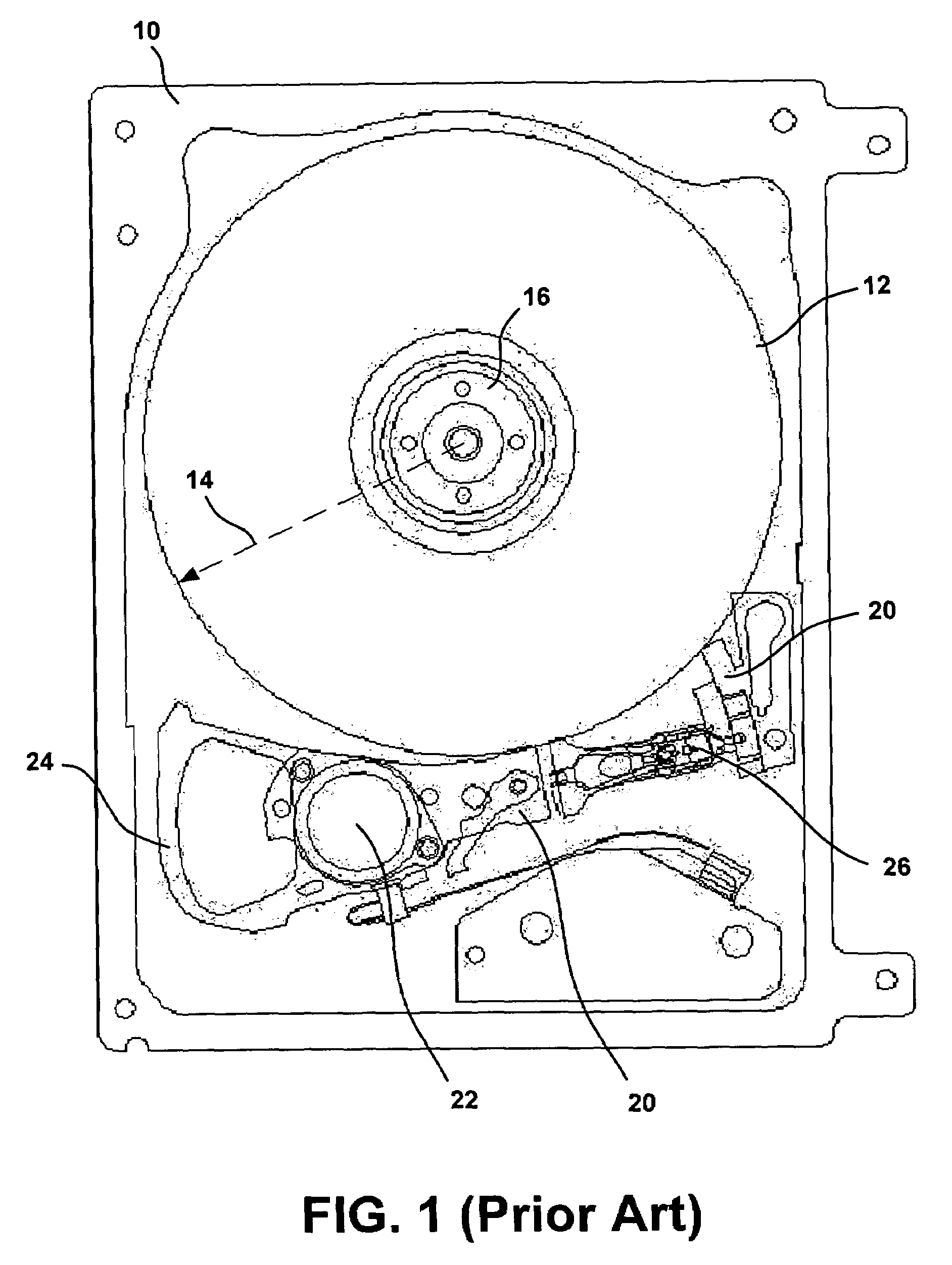
BACKGROUND OF THE INVENTION[0001]1. Field of the Invention[0002]The present invention relates generally to the field of information storage devices, and more particularly to air bearing sliders used in such devices.[0003]2. Background of the Art[0004]Information storage devices are used to retrieve and / or store data in computers and other consumer electronics devices. A magnetic hard disk drive is an example of an information storage device that includes one or more heads that can both read and write, but other information storage devices also include heads—sometimes including heads that cannot write.[0005]Recently the demand for smaller information storage devices has motivated the development of so-called micro-drives. Typically micro-drives are information storage devices that have been miniaturized and that therefore have smaller spinning disks than conventional devices. For example, a micro-drive may have disks with a diameter of less than 30 mm.[0006]FIG. 1 illustrates a micro...

Claims


Application Information

Patent Timeline
IPC IPC(8): G11B5/60
CPCG11B25/043G11B5/6005
Inventor SUN, BIAOHOSSAIN, FORHADYING, JI-FENGSLADEK, ERIC T.
Owner WESTERN DIGITAL TECH INC
Learn More