Method for implementing various functions in gigabit ethernet-passive optical network system and structure of ethernet frame employed in the same

a passive optical network and ethernet frame technology, applied in the field of passive optical networks, can solve the problems of inability to implement to-multipoint connection, low bandwidth, and relatively expensive equipment in the atm system

Inactive Publication Date: 2007-10-30
SAMSUNG ELECTRONICS CO LTD
View PDF13 Cites 22 Cited by
  • Summary
  • Abstract
  • Description
  • Claims
  • Application Information

AI Technical Summary

Benefits of technology

[0015]It is another object of the present invention to provide a frame format capable of effectively accommodating Gigabit Ethernet traffic in a GE-PON system.
[0017]It is yet another object of the present invention to provide a frame format capable of accommodating all types of layer-2 traffic such as the Ethernet, an ATM, etc. in a GE-PON system.
[0019]a) allowing the OLT to periodically transmit a synchronous signal to each of the plurality ONUs after initial drive such that each ONU is synchronized with the OLT in response to the synchronous signal periodically transmitted;
[0020]b) allowing the ONU synchronized with the OLT to identify a transmission start time of an initial registration request frame and a transmission time length included in a grant frame and allowing the ONU to transmit the initial registration request frame to the OLT after a random delay in order to avoid collision of initial registration request frames transmitted from the ONUs at the transmission time of the initial registration request frame;
[0025]b) allowing at least one ONU, newly driven among the ONUs, to be synchronized with a synchronous signal of downstream transmission;

Problems solved by technology

In order to obtain greater bandwidth, relatively costly equipment is needed in an ATM system and only provides limited bandwidth improvement (e.g., 622 Mbps).
Further, the point-to-multipoint connection is not implemented by the GE-PON and a format for a frame to be used between an OLT and an ONU in the GE-PON has not been defined.

Method used


Image

  • Method for implementing various functions in gigabit ethernet-passive optical network system and structure of ethernet frame employed in the same
  • Method for implementing various functions in gigabit ethernet-passive optical network system and structure of ethernet frame employed in the same
  • Method for implementing various functions in gigabit ethernet-passive optical network system and structure of ethernet frame employed in the same

Examples


Embodiment Construction

[0056]Now, preferred embodiments of the present invention are described in detail with reference to the drawings. In the drawings, the same or similar elements are denoted by the same reference numerals even though they are depicted in different drawings. Further, in the following detailed description of the present invention, a detailed description of known functions and configurations incorporated herein will be omitted when such a discussion is not necessary to the description of the present invention.

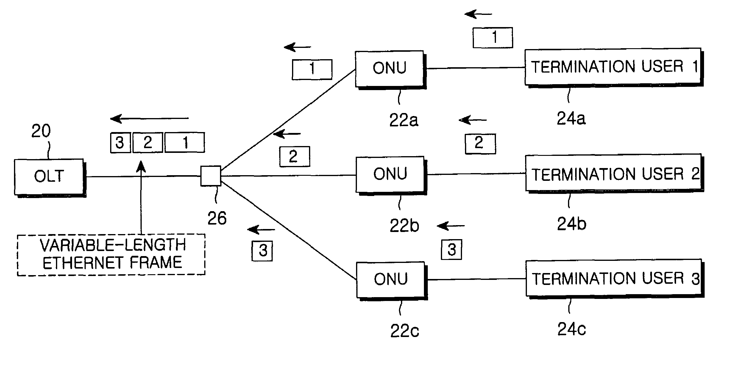
[0057]FIG. 3 is a view schematically showing a configuration of a GE-PON system in accordance with the present invention.

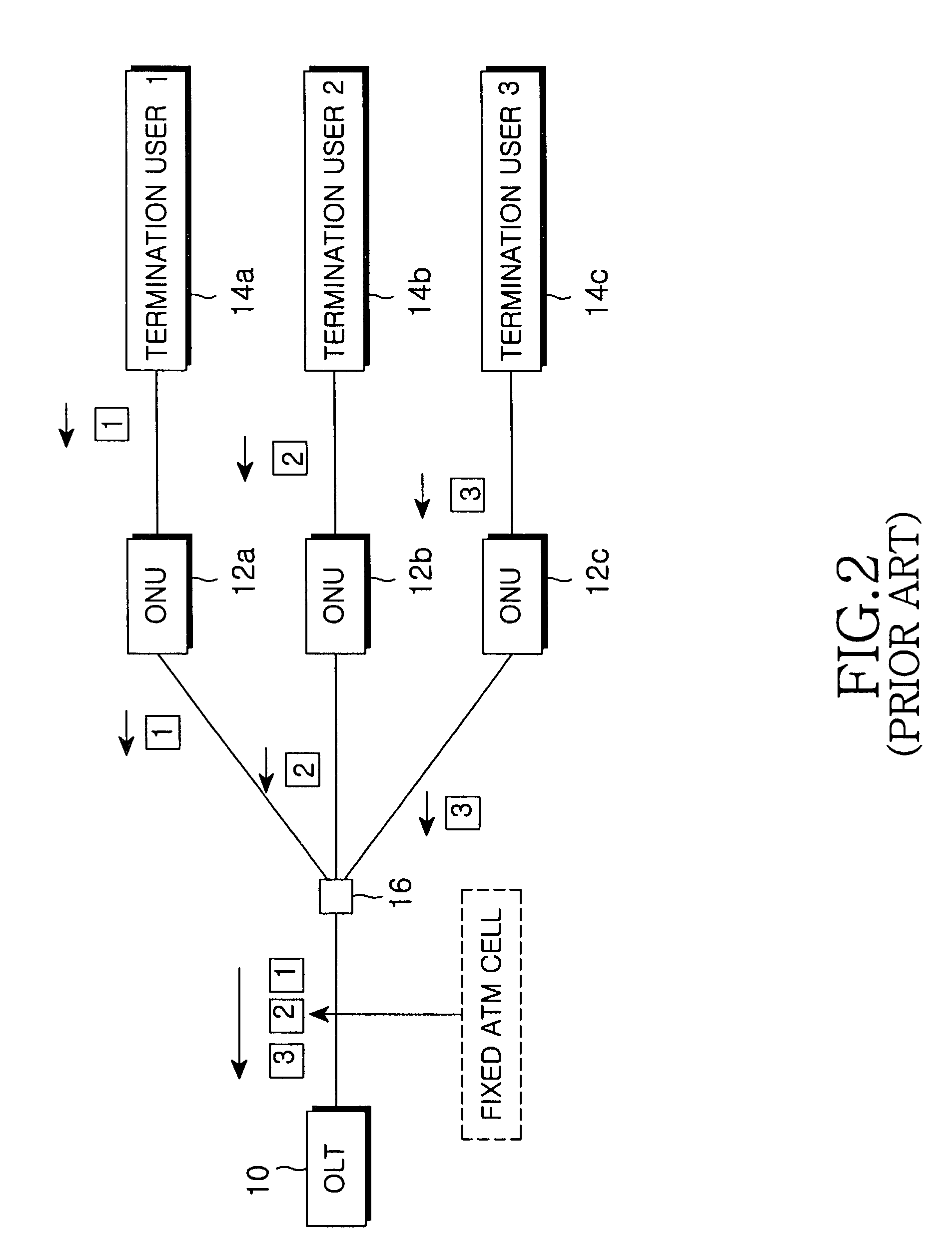
[0058]The GE-PON system shown in FIG. 3 comprises an OLT 20, an ODN 26 having an optical splitter as a passive device, ONUs 22a, 22b and 22c, and termination users 24a, 24b and 24c. A connection structure between components included in the GE-PON system shown in FIG. 3 is similar to that between components included in the ATM-PON system shown in FIG. 2. The GE-PON...


PUM


Abstract

A GE-PON (Gigabit Ethernet-Passive Optical Network) system is provided that configures upstream and downstream frames on the basis of a variable-length Ethernet frame. The GE-PON system employs TDM (Time Division Multiplexing) for upstream packet transmission in a tree structure for a point-to-multipoint connection. A structure of a frame format is also provided that is capable of effectively accommodating Gigabit Ethernet traffic in the GE-PON system and a method is provided for implementing various functions such as initial ONU registration, late ONU registration, ranging, and dynamic bandwidth allocation in the GE-PON system.

Description

CLAIM OF PRIORITY[0001]This application claims priority from an application entitled “METHOD FOR IMPLEMENTING VARIOUS FUNCTIONS IN GIGABIT ETHERNET-PASSIVE OPTICAL NETWORK SYSTEM AND STRUCTURE OF ETHERNET FRAME EMPLOYED IN THE SAME”, filed in the Korean Industrial Property Office on Jan. 17, 2002 and assigned Serial No. 2002-2765, the contents of which are hereby incorporated by reference.BACKGROUND OF THE INVENTION[0002]1. Field of the Invention[0003]The present invention relates to a passive optical network, and more particularly to a method for implementing various functions in a Gigabit Ethernet-Passive Optical Network (GE-PON) system and a structure of an Ethernet frame employed in same.[0004]2. Description of the Related Art[0005]To configure an optical subscriber network from a central office to a building or general home, a variety of network architectures such as an x-Digital Subscriber Line (xDSL), Hybrid Fiber Coax (HFC), Fiber To The Building (FTTB), Fiber To The Curb (F...

Claims


Application Information

Patent Timeline
Patent Type & Authority Patents(United States)
IPC IPC(8): H04J1/16H04L12/44H04J3/06H04L12/28H04Q11/00
CPCH04J3/0682H04L12/2801H04Q11/0067H04Q11/0066H04Q2011/0088H04Q11/0071H04Q2011/0079H04L12/28
Inventor LEE, MIN-HYOPARK, TAE-SUNGWON, SHIN-HEESUNG, WHAN-JINJANG, SOON-HOKIM, SU-HYUNGCHOI, DO-IN
Owner SAMSUNG ELECTRONICS CO LTD
Why Eureka
Try Eureka