Brake device for power tool

a technology of a power tool and a brake device, which is applied in the direction of brake systems, manufacturing tools, metal sawing accessories, etc., can solve the problems of injuring the operator, unfavorable operation, and the rotation of the output shaft for a while, so as to reduce the total weight and manufacturing cost, simplify the structure, and reduce the number of components.

Inactive Publication Date: 2007-11-06
HUSQVARNA AB
View PDF11 Cites 15 Cited by
  • Summary
  • Abstract
  • Description
  • Claims
  • Application Information

AI Technical Summary

Benefits of technology

[0011]According to the brake device of the present invention, the brake-activating block connects between the first throttle cable and the second throttle cable. These two throttle cables are used to control the position of the brake-activating block and thus to drive the brake-guiding pillar and the brake band to achieve the effect of braking and the release of braking without additionally providing a braking handle and a pivot member or the like. Therefore, its structure is greatly simplified, and the number of the components, the total weight and the manufacturing cost are reduced. Furthermore, since the brake is simultaneously controlled by the tension of the throttle cables, the operator only needs to release the throttle cables to automatically accomplish the brake without pressing any brake handle. Thus, it is very easy to operate the present invention.

Problems solved by technology

When the engine stops, although the engine does not provide any power to the output shaft, the output shaft still rotates awhile due to its inertia.
At this time, some undesired things might happen.
For example, the tool might further cut the machined work piece and thus influence the machining accuracy thereof, even might injure the operator.
In these brake devices for power tools mentioned above, although the output shaft can be quickly stopped once the engine stops, they still have some problems, such as components numerous, structure complicated, weight and manufacturing cost increased.

Method used


Image

  • Brake device for power tool
  • Brake device for power tool
  • Brake device for power tool

Examples


Embodiment Construction

[0018]Hereinafter, a detailed description relating to a brake device for a power tool in accordance with the present invention will be made with reference to the accompanying drawings.

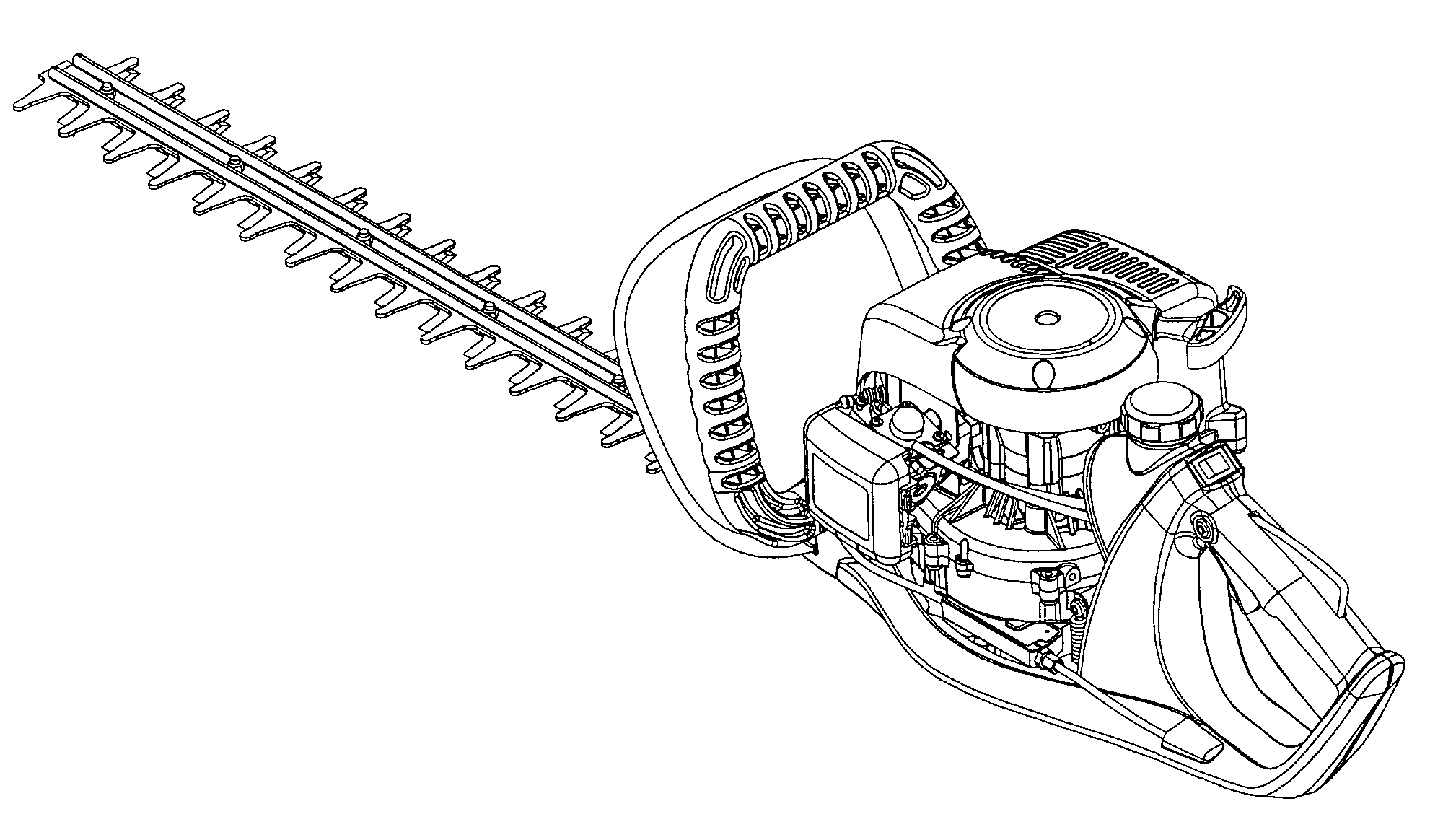
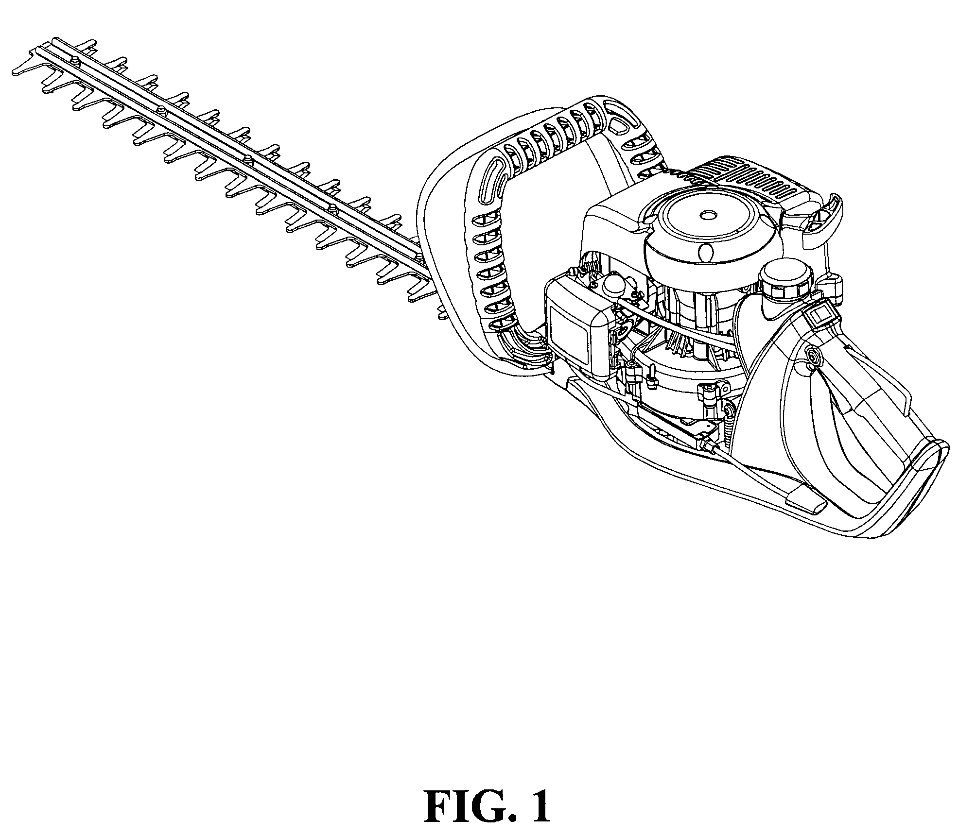
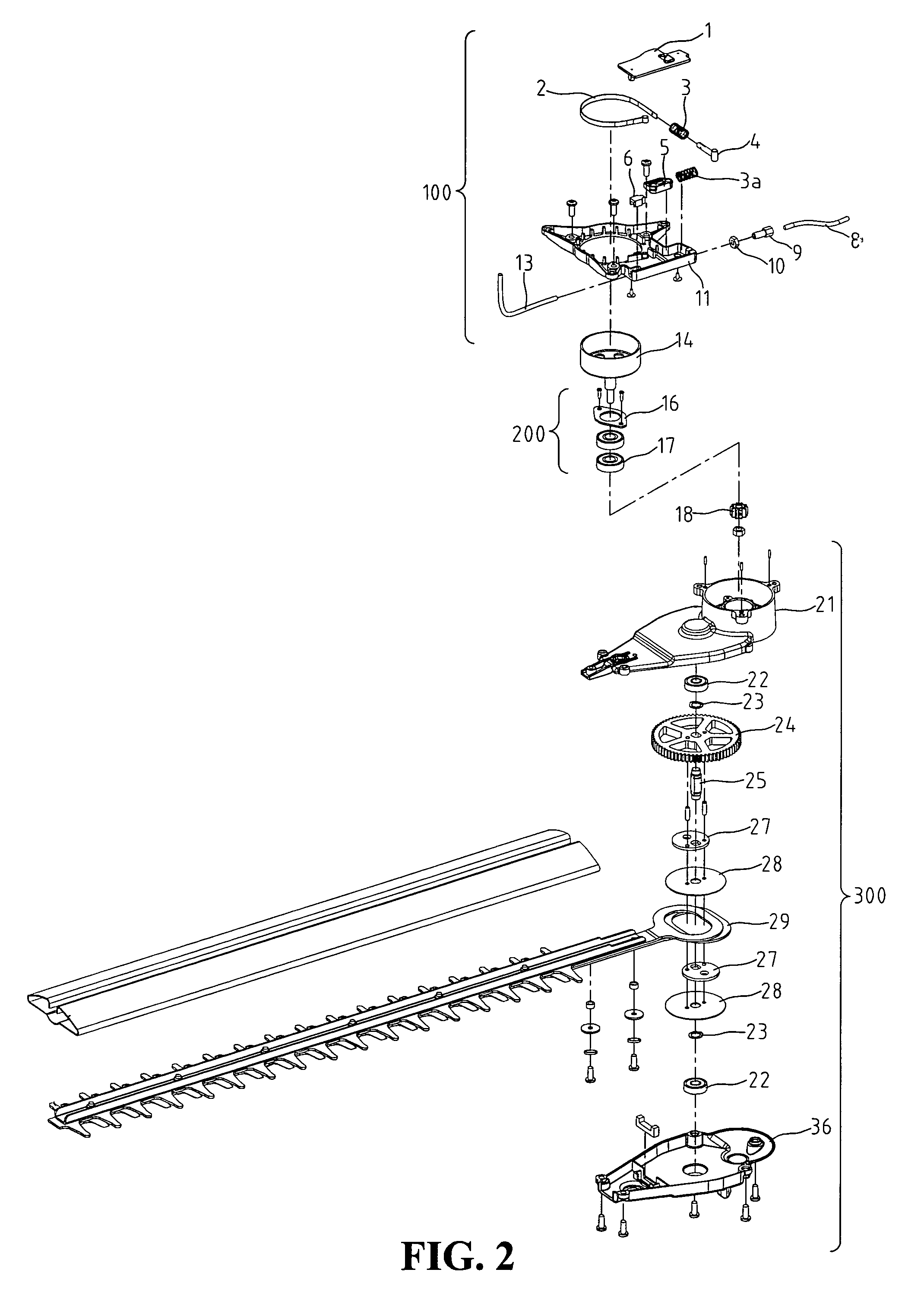
[0019]First, with reference to FIGS. 1 and 2, the brake device for a power tool of the present invention comprises a brake assembly 100, a bearing portion 200, a pinion 18 and a gearbox 300. The brake assembly 100 comprises a cover 1, a brake band 2, two springs 3 and 3a, a brake-guiding pillar 4, a brake-activating block 5, a first throttle cable 8, a second throttle cable 13, a locking block 6, a cable-guiding pillar 9, a brake base 11 and a brake drum 14. The cover 1 and the brake base 11 confines a casing of the brake assembly 100 for receiving the other components of the brake assembly therein.

[0020]The bearing portion 200 comprises a bearing plate 16, a bearing 17, and a pinion 18. The gearbox 300 comprises an upper cover 21, a bearing 22, a C-shaped retainer 23, a gear 24 and an output shaft 25,...


PUM

PropertyMeasurementUnit
lengthaaaaaaaaaa
timeaaaaaaaaaa
rotational speedaaaaaaaaaa

Abstract

A brake device for a power tool has a brake assembly, a bearing portion, a pinion and a gearbox. The brake assembly includes a brake base, a cover, a first throttle cable, a second throttle cable, a brake-activating block, a brake-guiding pillar, a brake band and a brake drum. The first throttle cable, the brake-activating block and the second throttle cable are linearly connected together in series. The brake-activating block is designed to abut against the brake-guiding pillar in a brake position and a release position, respectively. With the relative movement among the first throttle cable, the brake-activating block and the brake-guiding pillar, the abutting or separating state between the brake band and the brake drum can be easily controlled.

Description

BACKGROUND OF THE INVENTION[0001]1. Field of the Invention[0002]The present invention relates generally to a brake device for a power tool.[0003]2. The Prior Arts[0004]Many kinds of power tools are already well known, such as portable lawn mowers. In these power tools, an engine drives an output shaft mounted with a tool, such as circular saw and chain saw. When the engine stops, although the engine does not provide any power to the output shaft, the output shaft still rotates awhile due to its inertia. At this time, some undesired things might happen. For example, the tool might further cut the machined work piece and thus influence the machining accuracy thereof, even might injure the operator.[0005]Therefore, in order to reduce the risk of power tools, many kinds of brake device for power tools are proposed, such that the output shaft can be immediately stopped once the engine stops. Taiwan Patent Publication No. 221,936 disclosed a safety brake device for a sawing machine, in wh...

Claims


Application Information

Patent Timeline
Patent Type & Authority Patents(United States)
IPC IPC(8): B62B9/08
CPCF16D49/08F16D49/10F16D2127/001F16D2125/60F16D2121/16
Inventor LEE, HSIN-CHIH CHUNG
Owner HUSQVARNA AB
Why Eureka
Try Eureka