Microfluidic sieve using intertwined, free-standing carbon nanotube mesh as active medium

Inactive Publication Date: 2007-11-06
LAWRENCE LIVERMORE NAT SECURITY LLC
View PDF8 Cites 55 Cited by
  • Summary
  • Abstract
  • Description
  • Claims
  • Application Information

AI Technical Summary

Problems solved by technology

However, the lithographic process at the nano-scale has been extremely difficult in the past.
Other complications found in other on-chip separation device developments include, for example, the packing of columns with silica beads, which can complicate the fabrication process and drive up cost.

Method used


Image

  • Microfluidic sieve using intertwined, free-standing carbon nanotube mesh as active medium
  • Microfluidic sieve using intertwined, free-standing carbon nanotube mesh as active medium
  • Microfluidic sieve using intertwined, free-standing carbon nanotube mesh as active medium

Examples


first embodiment

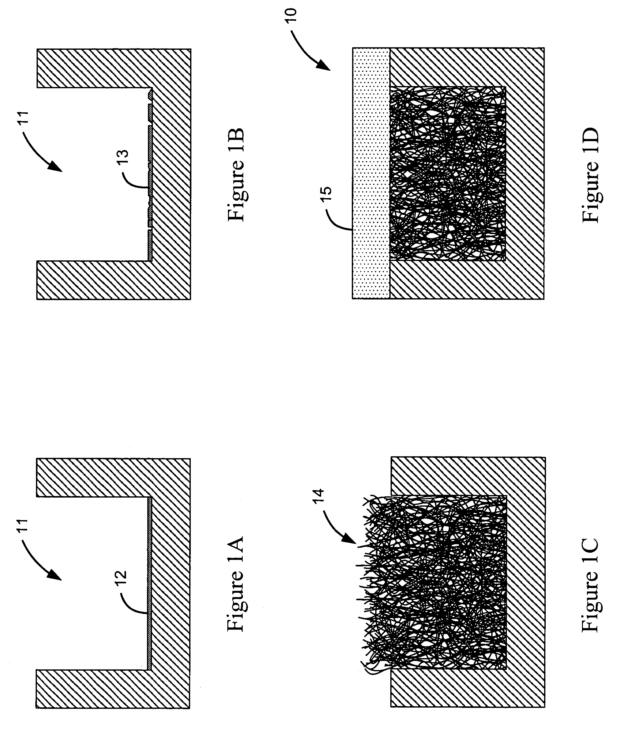
[0024]Turning now to the drawings, FIGS. 1A-D show the fabrication of the microfluidic sieve, generally indicated at reference character 10 (in FIG. 1D) using a CVD growth process. As shown in FIG. 1A, a channel 11 is first formed, e.g. by etching a groove, in a substrate made of silicon, fused silica or other patternable material. While a grooved channel configuration is shown having a floor surface and opposing vertical sidewall surfaces, it is appreciated that the channel and its cross-section may be configured with any suitable geometry, such as the curved cross-section shown in FIG. 7. Next a layer of iron catalyst 12 is deposited in the channel 11. The layer of iron catalyst is preferably a thin film layer having a thickness of about 5 nanometers, and deposited using thin film deposition techniques, such as evaporation or sputtering, with lithographic masking. It is appreciated, that as an alternative to an iron layer, colloidal iron nanoparticles and iron nanoparticles suppor...

second embodiment

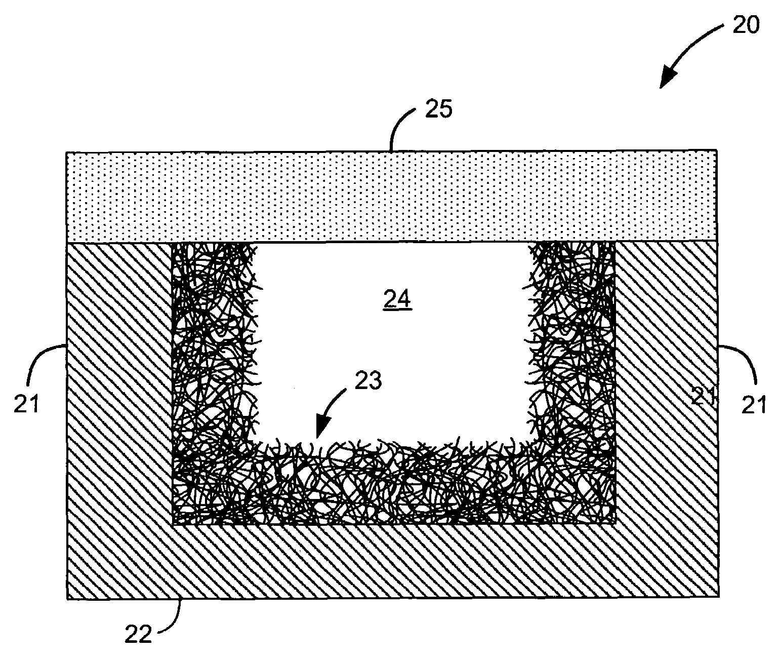
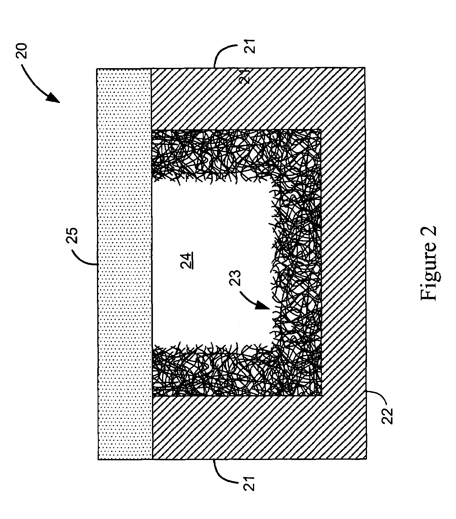
[0030]FIG. 2 shows the microfluidic sieve, generally indicated at reference character 20, wherein the carbon nanotube mesh 23 is surface-coated along the channel without filling the cross-section of the channel. In particular, the mesh 23 is surface coated along all sides of the channel, including the channel sidewalls 21 and the channel floor 22. In this manner, a gap 24 is formed through the mesh 23 and the channel, whereby flow may continue for certain applications, while target molecules or analytes are separated, concentrated and / or filtered in the mesh 23. The cover 25 is shown without the mesh surface-coated thereon, because, as previously discussed, the cover is typically bonded subsequent mesh growth within the channel. However, in this embodiment as well, the cover 25 may serve to pack any outgrowth of nanotubes along the top edge back within the channel.

[0031]Operation and use of the microfluidic sieve is shown in FIGS. 3 and 4. FIG. 3 shows a single channel embodiment 30...


PUM

PropertyMeasurementUnit
Pore sizeaaaaaaaaaa

Abstract

A microfluidic sieve having a substrate with a microfluidic channel, and a carbon nanotube mesh. The carbon nanotube mesh is formed from a plurality of intertwined free-standing carbon nanotubes which are fixedly attached within the channel for separating, concentrating, and/or filtering molecules flowed through the channel. In one embodiment, the microfluidic sieve is fabricated by providing a substrate having a microfluidic channel, and growing the intertwined free-standing carbon nanotubes from within the channel to produce the carbon nanotube mesh attached within the channel.

Description

CLAIM OF PRIORITY IN PROVISIONAL APPLICATION[0001]This application claims priority in provisional application filed on Jul. 3, 2002, entitled “Microfabricated Channel with Patterned Carbon Nanotube Array Active Element and a Fabrication Strategy for such Device” Ser. No. 60 / 393,425, by inventors Bakajin et al.[0002]The United States Government has rights in this invention pursuant to Contract No. W-7405-ENG-48 between the United States Department of Energy and the University of California for the operation of Lawrence Livermore National Laboratory.FIELD OF THE INVENTION[0003]The present invention relates to molecular and chromatographic separation mediums, and more particularly to a microfluidic sieve utilizing an intertwined free-standing carbon nanotube mesh as an active medium in a microfluidic channel for separating, concentrating, and / or filtering molecules flowed therethrough.BACKGROUND OF THE INVENTION[0004]Microfabricated fluidic systems are also being developed which employ...

Claims


Application Information

Patent Timeline
IPC IPC(8): B01D24/10B01D39/00B01D24/00
CPCB01D39/06B01J20/20B01J20/205B01J20/28004B01J20/28095B01J20/281B82Y15/00B82Y30/00B01J20/28007B01D15/34B01D2239/025Y10S977/745Y10S977/742
Inventor BAKAJIN, OLGICANOY, ALEKSANDR
Owner LAWRENCE LIVERMORE NAT SECURITY LLC
Why Eureka
Try Eureka