
Tool, method, and apparatus for removing burrs from bores

a technology of burrs and burrs, which is applied in the direction of turning equipment, boring/drilling equipment, milling equipment, etc., can solve the problems of significantly more expensive manufacturing process, achieve the effect of simplifying the introduction of tools, increasing rotational speed, and improving radial flexibility of shafts

Inactive Publication Date: 2007-11-06
GUHRING DR JORG
View PDF67 Cites 20 Cited by
  • Summary
  • Abstract
  • Description
  • Claims
  • Application Information

AI Technical Summary

Benefits of technology

[0009]The present invention is therefore based on the object of providing a tool and an apparatus, as well as a method, with which the deburring process can be carried out in an essentially more economical fashion, while remaining reliable and error-free.
[0045]A particular aspect of the present invention is that the (relatively high) flow medium pressure is used to fix the tool in the tool holding fixture axially and in the peripheral direction. This is because it has turned out that the cutting forces during deburring can easily be absorbed by the frictional force that arises when the fastening and fixing element is pressed against a retaining shoulder by the flow medium pressure. This is further facilitated in that the fastening and fixing element can be given a greater diameter than the cutting head.

Problems solved by technology

However, the great precision required for this has the consequence that the manufacturing process becomes significantly more expensive.

Method used


Image

  • Tool, method, and apparatus for removing burrs from bores
  • Tool, method, and apparatus for removing burrs from bores
  • Tool, method, and apparatus for removing burrs from bores

Examples


Embodiment Construction

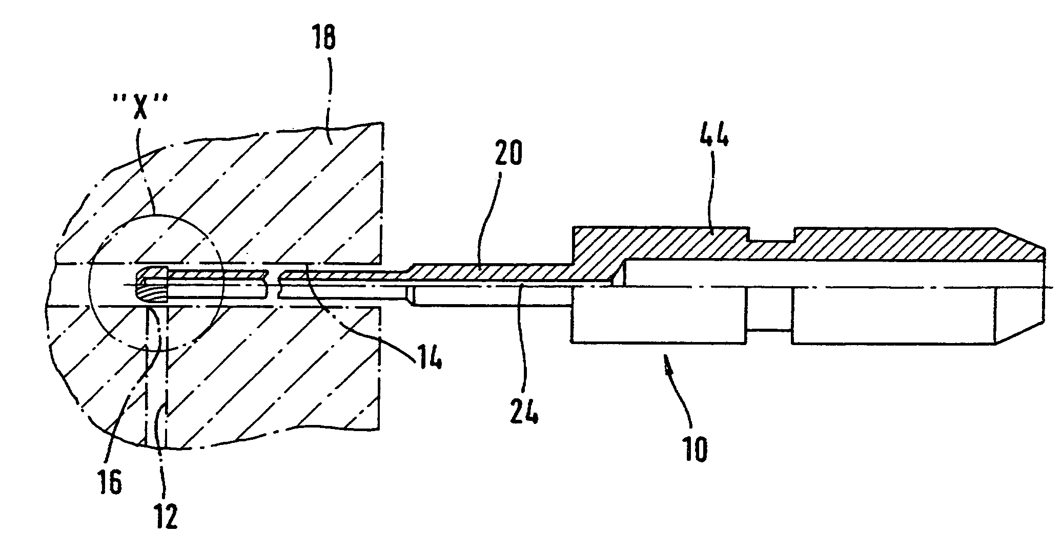
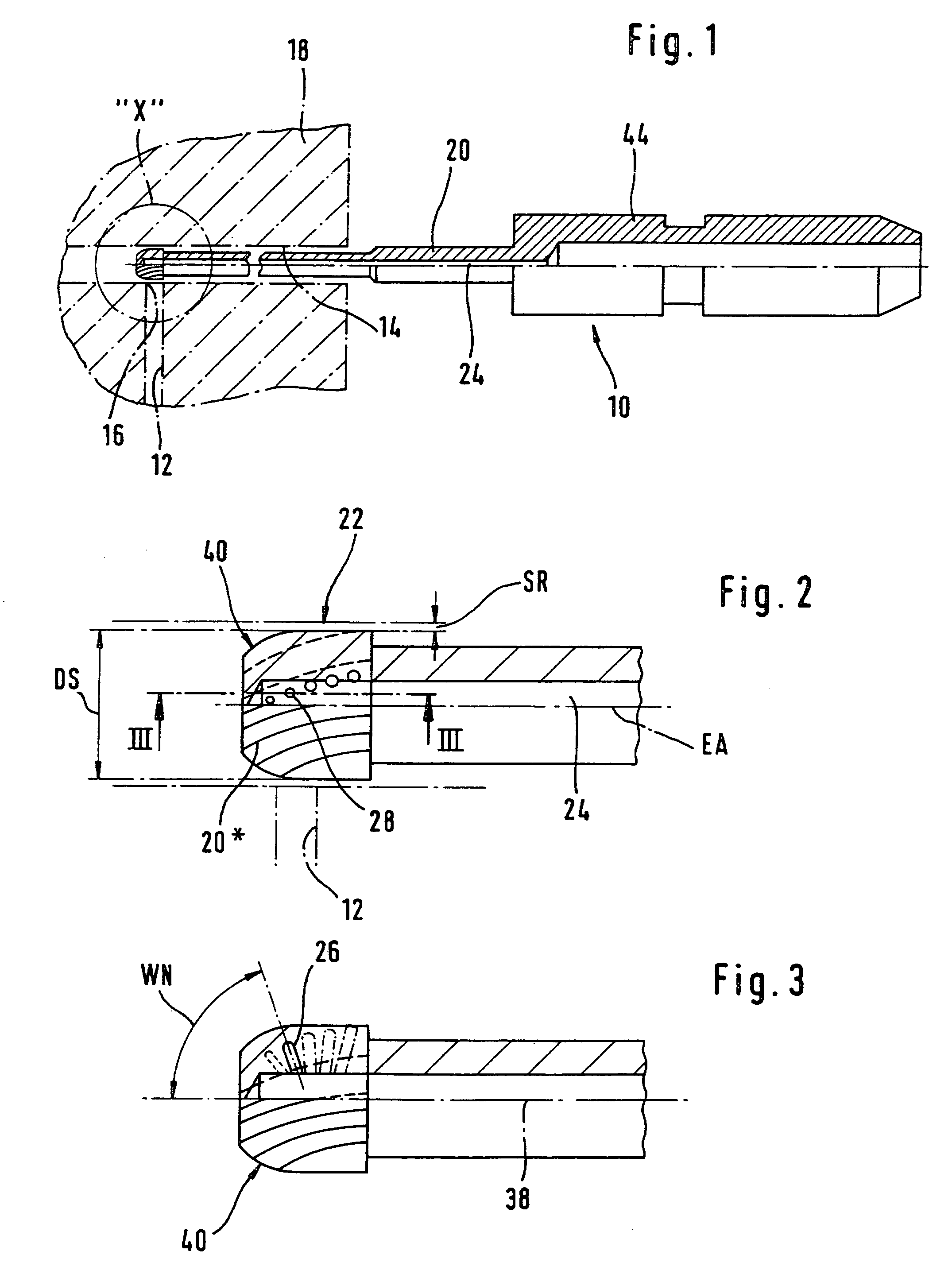
[0071]In FIG. 1, reference character 10 designates a rotationally driven, preferably rotationally symmetrical post-processing tool in its construction as a deburring tool, with which it is possible to debur, at their radially inner ends 16, bores 12 that open laterally into an essentially cylindrical recess 14 in a workpiece 18, in a particularly economical manner that is as reliable as possible. However, here it should also already be emphasized that the tool can also be static, and that the workpiece can be placed into rotational motion, instead of or in addition to the tool. Moreover, the tool can also be used for the deburring of the openings of recess 14.

[0072]The tool is for example formed as a milling tool, a boring tool, in particular a deep-hole boring tool, a straight-fluted boring tool or a spiral boring tool, or a reamer. It is decisive that it has at least one cutting edge 20* that can execute a machining.

[0073]In the tool, on a shaft 20 there is a cutting head 22 that ...


PUM

PropertyMeasurementUnit
diameteraaaaaaaaaa
angleaaaaaaaaaa
central angleaaaaaaaaaa

Abstract

A preferably rotationally driven tool is specified for the deburring of openings, such as for example bores that open laterally into an essentially cylindrical recess. The tool has a cutting head that is seated on a shaft and that has at least one cutting edge that extends, at least in segments, in the axial direction. So that the deburring can be carried out reliably and with the lowest possible expense, a radial force-producing device is integrated into the tool, for example in the form of at least one internally situated flow medium channel, from which at least one branch channel goes out that opens in the area of the cutting head or in the vicinity thereof, preferably at a peripheral distance to the at least one cutting edge, in the external peripheral surface thereof. Because the diameter of the cutting head is selected such that it can be introduced into the recess with radial play, the radial force produced either upon rotation of the tool or through the feeding in of a flow medium under pressure has the result that the cutting head is elastically deflected radially, through which the inner surface of the recess is gently processed, and thereby enabling reliable execution of the deburring process.

Description

CROSS-REFERENCE TO RELATED APPLICATION[0001]This application is a continuation in part of U.S. patent application Ser. No. 10 / 246,530, filed on Sep. 19, 2002 now abandoned, which is expressly incorporated by reference herein.BACKGROUND OF THE INVENTION[0002]1. Field of the Invention[0003]The present invention relates to a preferably rotationally driven tool for deburring bores, such as for example bores that open laterally into a recess or opening that is for example cylindrical, according to the preamble of claim 1. In addition, the present invention relates to an apparatus and to a method for deburring bores of this sort, in which a tool according to the present invention is intended to be used.[0004]2. Description of the Related Art[0005]The deburring of bores that open laterally into a recess that is for example cylindrical presents a great problem. Bores of this sort, for example in the area of automotive technology (in the case of radial bores that open into a central axial bo...

Claims


Application Information

Patent Timeline
Patent Type & Authority Patents(United States)
IPC IPC(8): B23C3/00B23C5/10B23B51/10B23C1/06B23C3/12B23D77/00
CPCB23B51/105B23D77/006B23B2260/068B23B2270/24B23D2277/60Y10T409/303808Y10T408/45Y10T407/1946Y10T408/455Y10T408/907Y10T408/9097
Inventor GAISER, GILBERTHEBISCH, HARALD
Owner GUHRING DR JORG
Learn More