Pulp flaker

a technology of pulp flaker and pulp, which is applied in the field of pulp flaker, can solve the problems of pulp having a sinusoidal profile, achieve the effects of reducing the size of the pulp, preventing the scattering of pulp, and ensuring the uniformity of the mass flow of pulp

Inactive Publication Date: 2007-11-06
WEYERHAEUSER CO
View PDF15 Cites 18 Cited by
  • Summary
  • Abstract
  • Description
  • Claims
  • Application Information

AI Technical Summary

Benefits of technology

[0004]The present invention is related to methods for conveying, mixing, leveling, and flaking dewatered pulp to produce pulp flakes suitable to be used in the jet dryer described in the '143 application. The present invention is also related to a method for producing a consistent flow rate of pulp; and, for producing uniform pulp flakes in terms of pulp flake size and pulp flake moisture content. One embodiment of a method includes introducing a dewatered pulp to a rotating shaftless screw conveyor. The rotating shaftless screw conveyor can simultaneously mix and convey the pulp along a length of the screw conveyor. The pulp is deposited from the screw conveyor onto a moving belt conveyor via a chute. The chute retains the pulp, prevents scattering of the pulp on the belt conveyor, and results in a pulp pile of uniform width. Even with the use of a chute, when the pulp is deposited from the chute onto the belt conveyor, the pulp can form uneven quantities of pulp along a length of belt conveyor due to the nature of the rotating shaftless screw conveyor design, and can result in the pulp having a sinusoidal profile. The pulp is flattened out, or leveled, with a rotary doctor located above the belt conveyor to produce a substantially even rate of mass flow of pulp along a length of belt conveyor. Substantially even, uniform, and consistent quantities of pulp per unit time can then be fed from the belt conveyor to a pulp flaker that translates into an even rate of mass flow to the jet dryer. The pulp flaker can reduce the size of the pulp into pulp flakes of consistent or uniform size.
[0008]The present invention thus provides a consistent rate of mass flow of pulp for dryers. The pulp flakes leaving the flaker are, on average, consistently about one-sixteenth to about one-half of an inch in size. As a result, the moisture content of the pulp flakes varies less with the methods described herein as compared with the airlock.

Problems solved by technology

Even with the use of a chute, when the pulp is deposited from the chute onto the belt conveyor, the pulp can form uneven quantities of pulp along a length of belt conveyor due to the nature of the rotating shaftless screw conveyor design, and can result in the pulp having a sinusoidal profile.

Method used


Image

  • Pulp flaker
  • Pulp flaker
  • Pulp flaker

Examples


Embodiment Construction

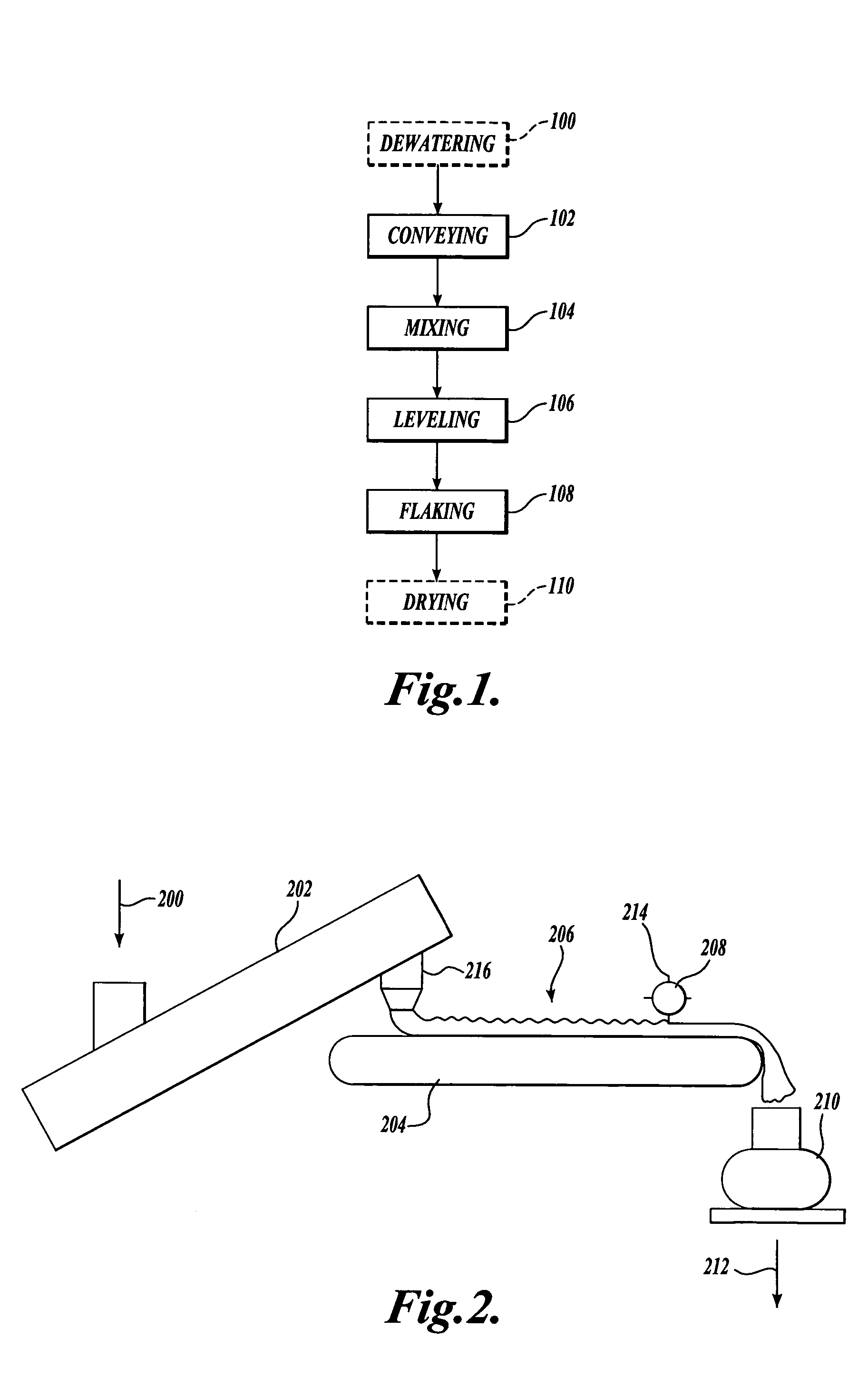
[0019]Referring to FIG. 1, the present invention is related to methods for conveying 102, mixing 104, leveling 106, and flaking 108, dewatered pulp into pulp flakes of uniform small size and moisture content to improve the operation of a dryer. In the '143 application referred to above, an airlock was used immediately prior to a jet dryer. The airlock proved unsatisfactory. “Jet drier” as used herein means any dryer that accelerates air into a loop conduit enabling the simultaneous drying and singulation of a substance flowing through the conduit. Reference is made to the '143 application for a fuller description of jet dryers and their operation. FIG. 1 of the '143 application (provided as FIG. 8 herein) shows a shaftless screw conveyor 40, followed by an airlock 60 which then feeds pulp into the jet dryer 20. According to one embodiment of the present invention, in place of the airlock 60, a belt conveyor with a leveling apparatus and a pulp flaker are substituted for the airlock ...


PUM

PropertyMeasurementUnit
lengthaaaaaaaaaa
distanceaaaaaaaaaa
distancesaaaaaaaaaa

Abstract

Methods for conveying, mixing, leveling, and flaking dewatered pulp to produce pulp flakes suitable to be used in a dryer. Methods for producing a consistent flow rate of pulp, and, for producing uniform pulp flakes in terms of pulp flake size and pulp flake moisture content. A method includes introducing a dewatered pulp to a rotating shaftless screw conveyor. The pulp is deposited from the screw conveyor onto a moving belt conveyor through a chute. The pulp is leveled with a rotary doctor located above the belt conveyor to produce a substantially even rate of mass flow of pulp along a length of belt conveyor. Uniform and consistent quantities of pulp per unit time can then be fed from the belt conveyor to a pulp flaker that then translates into an even rate of pulp mass flow to the dryer.

Description

FIELD OF THE INVENTION[0001]The present invention is related to a process for producing a consistent flow rate of pulp; and, for producing uniform pulp flakes in terms of size and moisture content.BACKGROUND OF THE INVENTION[0002]A process to produce dried singulated cellulose pulp fibers is described in U.S. application Ser. No. 09 / 998,143 (hereinafter the '143 application), filed on Oct. 30, 2001, which is incorporated herein by reference in its entirety, and is assigned to the assignee of the present application. A representative schematic illustration of the process of the '143 application is provided herein as FIG. 8. One process described in the '143 application which is depicted in FIG. 8, uses a rotary airlock 60 interposed between a jet dryer 20 and the pulp feed system. The rotary airlock 60 comprises a single rotor with vanes.[0003]However, it has been determined that the airlock described in the '143 application negatively affected the operation of the jet dryer, resulti...

Claims


Application Information

Patent Timeline
Patent Type & Authority Patents(United States)
IPC IPC(8): D21B1/04D21B1/00D21B1/06D21CD21C3/26D21C9/00D21C9/18D21HD21H15/08F26B7/00
CPCD21B1/068D21H15/08D21C9/00
Inventor DEZUTTER, RAMON C.TVETER, CHRISTOPHER Q.
Owner WEYERHAEUSER CO
Why Eureka
Try Eureka