
Orientation independent liquid fuel reservoir

a liquid fuel reservoir and orientation independent technology, applied in the field of orientation independent liquid fuel reservoirs, can solve the problems of short circuit in the cell, achieve the effect of reducing or eliminating the pumping requirements of the liquid fuel cell device, weight reduction and/or cost savings

Inactive Publication Date: 2007-11-06
MP FOAM DIP +1
View PDF94 Cites 17 Cited by
  • Summary
  • Abstract
  • Description
  • Claims
  • Application Information

AI Technical Summary

Benefits of technology

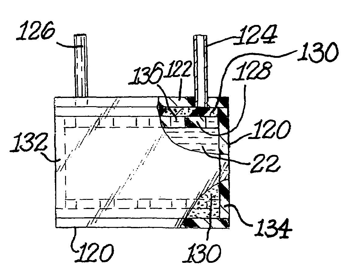
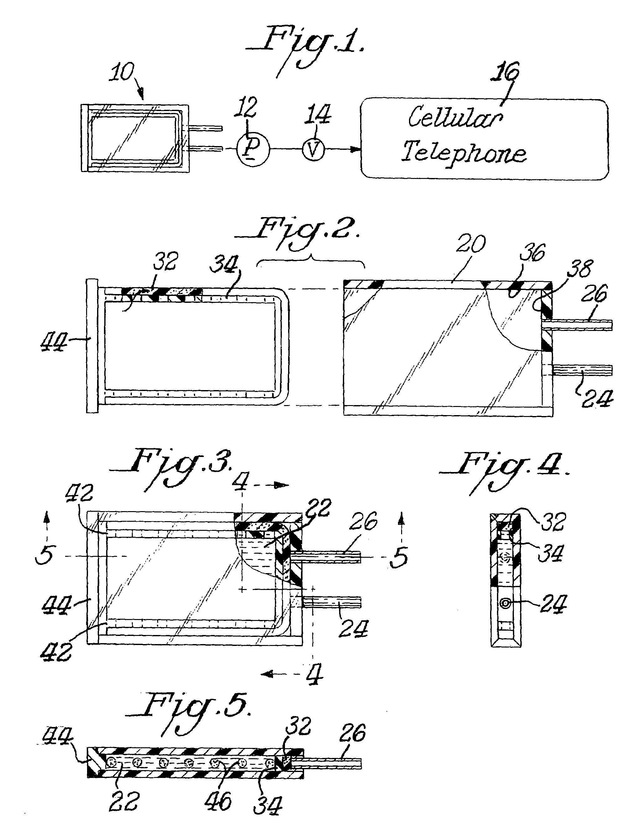
[0020]In some of the embodiments of the liquid fuel reservoir of the invention, the container of the reservoir can further comprise a pressurized pallet or bladder inside, which can push the liquid fuel stored in the container out of the outlet passageway of the container to deliver the liquid fuel to a liquid fuel cell without the application of suction at the outlet passageway or using any pump or liquid drawing means, such as a wicking material, at the outlet passageway. The combination of the capillarity of the wicking structure and the positive pressure generated by the pressurized pallet or bladder will allow the liquid fuel to be delivered, independent of the orientation, to the fuel cell with a fuel reservoir of lower manufacturing cost than fuel reservoirs of the prior art. Instead of the pressurized pallet or bladder, the positive pressure may be obtained by introducing a pressurized or pressurizing gas into the liquid fuel reservoir via an inlet port of the reservoir, wherein the inlet port does not have any valve that impedes or prevents any inflow of gas and the pressurized or pressurizing gas imparts sufficient pressure on the liquid fuel stored in the liquid fuel reservoir to push the liquid fuel out of the reservoir via the outlet passageway of the reservoir. Since an air pump may already be present in certain fuel cell devices, the positive pressure arrangement could reduce the weight by eliminating the need for a liquid pump. Reducing the weight of the liquid fuel reservoir system would potentially allow the fuel reservoir to carry more liquid fuel. Regardless whether the air pump is present in the fuel cell device, the positive pressure arrangement minimizes the complexity of the reservoir design by eliminating the use of vent valves and a self-priming step of a liquid pump. Simplifying the design complexity would make the fuel delivery system less costly.
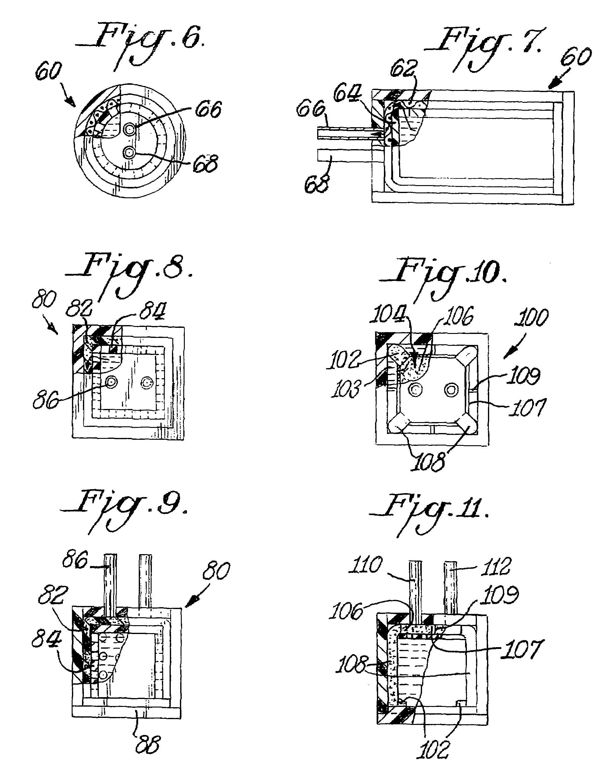
[0021]The pressurized pallet or bladder can be made by providing a container of the reservoir, wherein the container comprises first and second compartments, which can be separated by a flexible membrane. The first compartment comprises at least one wall, a port through the at least one wall of the compartment, at least one extremity remote from the outlet and a wicking structure (a) being in fluid communication with the outlet; and (b) extending from proximate the at least one extremity to proximate the outlet in order to place the at least one extremity in fluid communication with the outlet, in any orientation of the container, and at substantially any stage of liquid fuel depletion, to permit liquid fuel located proximate the at least one extremity to be wicked to the outlet. Preferably, the wicking structure has a solid wicking structure volume which is no more than 50% of the capacity of the first compartment. The port of the first compartment optionally has a valve that can control the inflow and / or outflow of fluid. Alternatively, the port can be plugged when not in use. The second compartment comprises at least one wall and a port through the at least one wall of the compartment. A piece of compressible porous material, preferably a foam such as polyurethane foam, is placed inside the second compartment and then covered with the flexible membrane, wherein the volume of the compressible porous material in a relaxed state is larger than the combined internal capacities of the first and second compartments. Alternatively, the flexible membrane is laminated to the compressible porous material to make assembly easier. The second compartment is attached to the first compartment with the flexible membrane separating the two compartments, so that the internal space inside both compartments is completely filled with the compressible porous material and the flexible membrane, with the compressible porous material slight compressed. Alternatively, the flexible membrane can be eliminated by applying a coating to the surface of the compressible porous material of the second compartment, wherein the coating renders the compressible porous material impermeable to the liquid fuel.
[0026]The flow rate of the liquid fuel out of the first compartment can be controlled with a valve arrangement installed between the port of the first compartment and the liquid fuel cell. If necessary, the flow rate of the liquid fuel can be augmented with an auxiliary pump. Since the liquid fuel is delivered from the first compartment by the positive pressure generated by the compressed porous material, the pumping requirements for the liquid fuel cell device can be reduced or eliminated resulting in weight reduction and / or cost savings. Once all of the liquid fuel stored in the first compartment is consumed, the liquid fuel reservoir can be removed and the whole operating cycle can be repeated.
[0027]Optionally, the second compartment is used as a receptacle to hold any spent fuel or byproducts produced by the liquid fuel cell, wherein the spent fuel or byproducts are introduced into the second compartment via the port of the second compartment. The spent fuel or byproducts forced from the liquid fuel cell can fill the void in the compressible porous material of the second compartment created by the discharge of the liquid fuel from the first compartment. Thus, the second compartment can function as a storage for the spent fuel or byproducts for later disposal. The volume of the spent fuel or byproducts stored in the second compartment can equal the volume of the liquid fuel delivered from the first compartment. The introduction of the spent fuel or byproducts into the second compartment may also aid the compressed porous material in applying positive pressure on the liquid fuel stored in the first compartment.

Problems solved by technology

Cross-over results in a short circuit in the cell since the electrons resulting from the oxidation reaction do not follow the current path between the electrodes.
The problem is particularly acute for fuel cells intended to be used in portable applications, such as in consumer electronics including cell phones, where the fuel cell orientation with respect to gravitational forces will vary.

Method used


Image

  • Orientation independent liquid fuel reservoir
  • Orientation independent liquid fuel reservoir
  • Orientation independent liquid fuel reservoir

Examples


example 1

[0196]An experiment was conducted to determine the removal of non-volatile residues (NVR), as impurities, from methanol by the following impurities scavenging substances: granulated carbon (203-67), granulated carbon (203-75A), Norit Darco G-60 (203-75B) and Calgon carbon (203-75D). NVR had been extracted from a piece of foam into the methanol to form a methanol solution containing NVR to be used in the impurities removal experiment. Separately for each of the above impurities scavenging substances, approximately 150 ml of the methanol solution containing NVR was placed in a beaker with a magnetic stir bar and the impurities scavenging substance was added in the amount shown in the table below, mixed for at least 24 hours, subjected to filtration if necessary to remove the impurities scavenging substance, distilled to dryness and weighed to determine the amount of NVR remaining. A control run was performed to determine the weight percent of NVR in the methanol not exposed to the imp...

example 2

[0198]A liquid fuel reservoir of the invention containing a 90-pore, reticulated ether foam felted to firmness 7 as the wicking structure was filled with clean methanol and connected to a syringe pump and pressure transducer. The syringe-pump was set to dispense 10 mL / hr and the pressure flow data were recorded until air entered the system. Negative pressure data were plotted over time (see FIG. 79A with the reservoir standing up, i.e. with both inlet and outlet oriented at the top of the reservoir, and FIG. 80A with the reservoir upside down, i.e. with both inlet and outlet oriented at the bottom of the reservoir).

[0199]In a separate experiment, the liquid fuel reservoir containing a 90-pore, reticulated ether foam felted to firmness 7 as the wicking structure was filled with clean methanol and connected to a syringe pump and pressure transducer. The syringe-pump was set to withdraw 10 mL / hr and the pressure flow data were recorded until air entered the system. Positive pressure da...


PUM

PropertyMeasurementUnit
densityaaaaaaaaaa
densityaaaaaaaaaa
densityaaaaaaaaaa

Abstract

A fuel reservoir for a liquid fuel cell particularly useful for portable electronic devices or for a reformer, includes (a) a container defining a volume for holding a liquid fuel; (b) a wicking structure positioned within the volume and into which at least one portion of the liquid fuel wicks and from which said liquid fuel subsequently may be metered, such as by pumping; (c) a retainer to hold the wicking structure in a desired orientation within the container; and (d) an outlet for the liquid fuel that is in communication with the wicking structure. A method of dispensing liquid fuel and a method of assembling a fuel cartridge are also disclosed.

Description

CROSS-REFERENCE TO RELATED APPLICATIONS[0001]The instant application claims the benefit of U.S. Provisional Patent Application Nos. 60 / 411,352, 60 / 411,353, and 60 / 411,359, all filed on Sep. 18, 2002, as well as U.S. Provisional Patent Application No. 60 / 460,406 filed on Apr. 7, 2003. The disclosures of all these provisional applications are incorporated by reference. The instant application is also a continuation-in-part application of U.S. Non-Provisional patent application Ser. No. 10 / 329,776, filed on Dec. 27, 2002, the disclosure of which is also herein incorporated by reference.[0002]This invention relates to liquid fuel cells in which the liquid fuel is directly oxidized at the anode. In particular, it relates to the reservoir for holding and metering or delivering the liquid fuel to the anode of a liquid fuel cell. This invention also relates to liquid fuel feed systems for micro fuel cell reformers.BACKGROUND OF THE INVENTION[0003]Electrochemical fuel cells convert reactants...

Claims


Application Information

Patent Timeline
Patent Type & Authority Patents(United States)
IPC IPC(8): H01M8/00H01M2/02H01M2/08H01M2/14H01M8/10B67D3/00F02MH01M8/02H01M8/04
CPCH01M8/04186H01M8/04208H01M8/1011Y02T90/32H01M2250/20Y02E60/523Y02E60/522H01M2008/1095Y02E60/50Y02T90/40
Inventor KINKELAAR, MARK R.OVERK, KENNETH P.PANARELLO, SALVATORE C.LOVETTE, JOSEPH W.TUINMAN, ROELAND J.GOOD, RICHARD M.
Owner MP FOAM DIP
Learn More