Electric rotating machine with bearing seals
a technology of bearing seals and rotating machines, which is applied in the direction of mechanical energy handling, machines/engines, mechanical apparatus, etc., can solve the problems of increasing the cost of electric rotating machines, reducing the thickness of oil films locally, and reducing the purity of cooling gas. , to achieve the effect of suppressing the reduction in cooling gas purity
- Summary
- Abstract
- Description
- Claims
- Application Information
AI Technical Summary
Benefits of technology
Problems solved by technology
Method used
Image
Examples
first embodiment
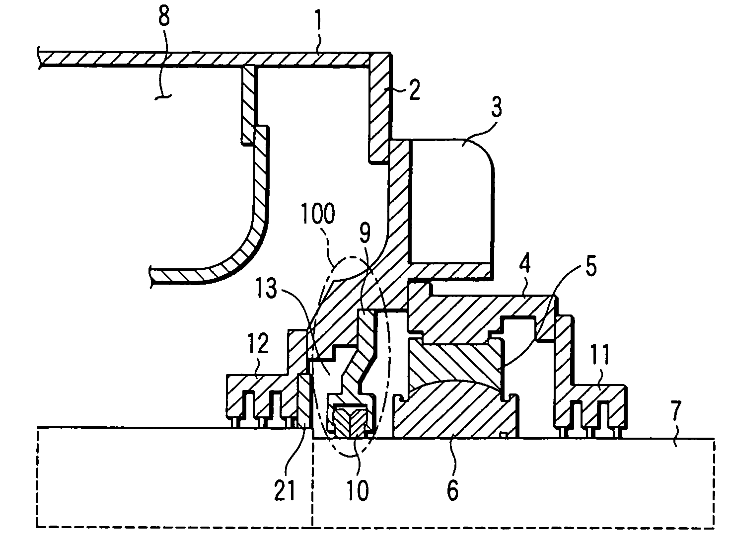
[0065]Now, embodiments of an electric rotating machine including a shaft seal device according to the invention will be explained with reference to the drawings. FIG. 1 is an axial direction cross-sectional view of an area around a shaft seal device of an electric rotating machine showing the invention, and it differs from FIG. 28 which shows the prior art described above, in that a brush seal 21 serving as a sealing mechanism which does not require a lubricating member formed of a seal brush is provided at a seal cavity 13 of an internal oil deflector 12. In other words, in this embodiment, a shaft seal device 100 is formed of a seal ring 10 mounted inside a seal casing 9 and the brush seal 21 mounted on the internal oil deflector 12.
[0066]In the thus configured shaft seal device 100 of the electric rotating machine according to the first embodiment, a hydrogen gas 8 which is used as a cooling medium inside the machine attempts to enter the seal cavity 13 from the gap between the i...
second embodiment
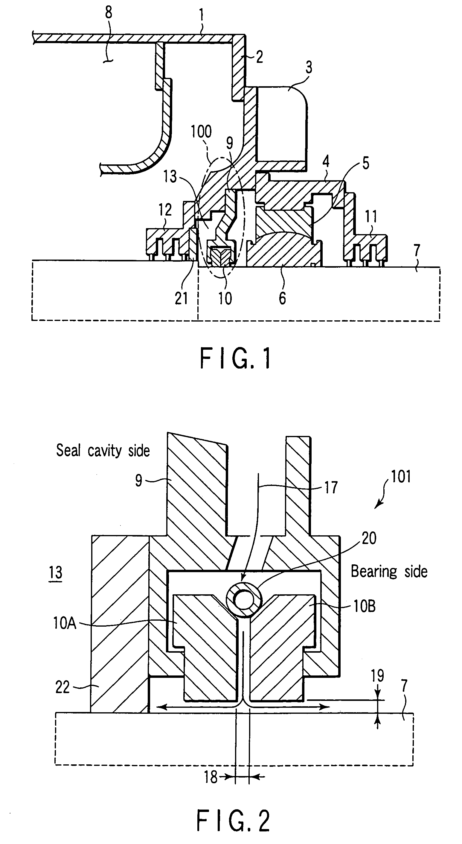
[0069]Next, the shaft seal device of the electric rotating machine of the invention will be described with reference to FIG. 2. That is, a structure is provided in which a brush seal 22 which is a sealing mechanism is mounted at the seal cavity 13 side of the seal casing 9 which holds seal rings 10A and 10B which are the same as that of the prior art is mounted.
[0070]In a shaft seal device 101 of the second embodiment having this configuration, the sealing oil is caused to flow from an axial direction gap 18 of the seal ring 10A at the seal cavity side and the seal ring 10B at the bearing side to narrow gaps 19 between the seal ring 10A and rotating shaft 7, and between the seal ring 10B and the rotating shaft 7, respectively, and then caused to flow out to the seal cavity side and the bearing side, respectively. However, because the brush seal 22 is provided at the seal cavity 13 side, the sealing oil 17 which flows out to the seal cavity 13 side never flows out to the seal cavity ...
third embodiment
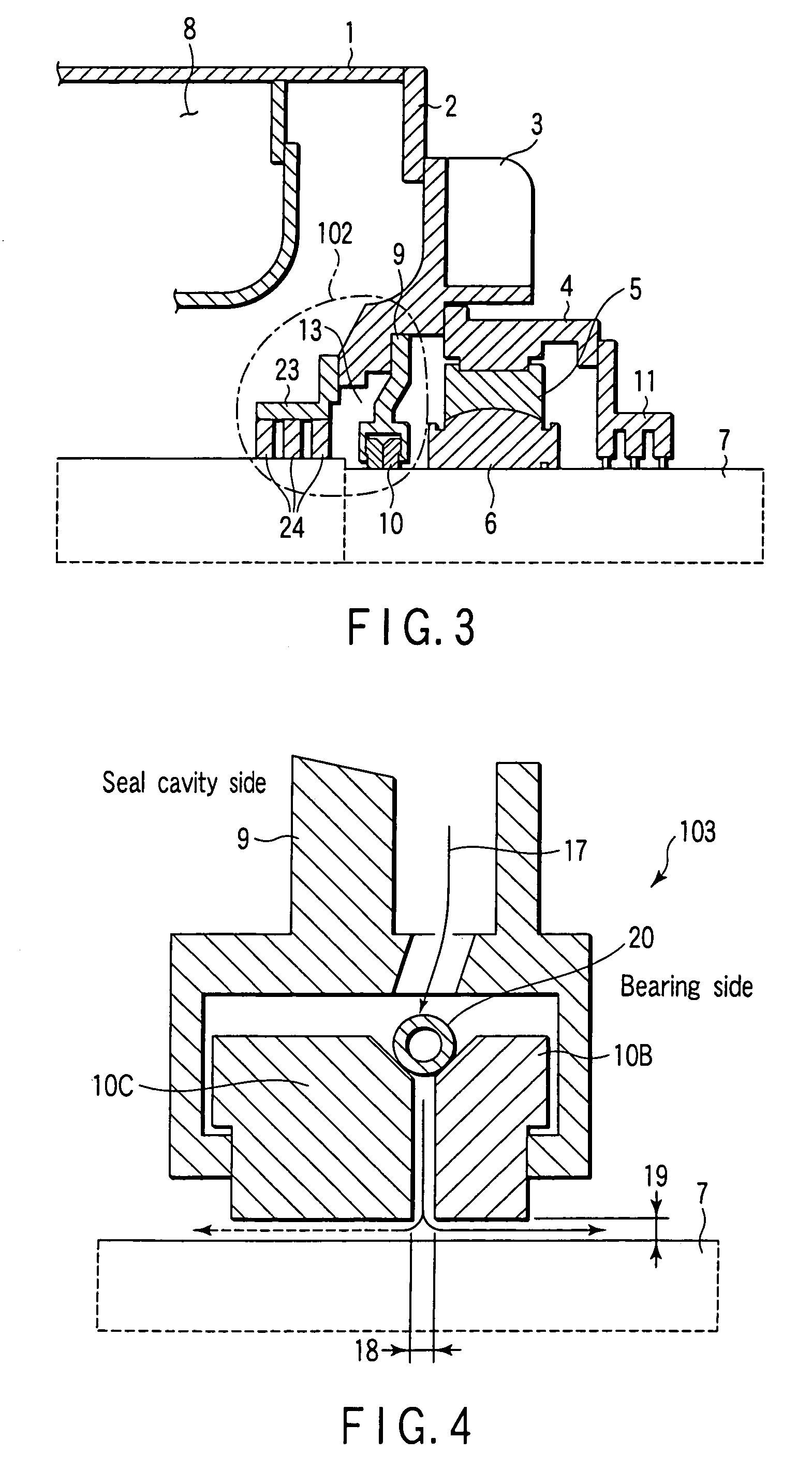
[0072]Next, the shaft seal device of the electric rotating machine of the invention will be described with reference to FIG. 3. In this embodiment, the internal oil deflector 12 of FIG. 28 is not provided, and a sealing mechanism which does not require a lubricating member, e.g., a seal brush 24, is supported by a brush seal holder 23 and is mounted to an end bracket 3 at this portion. The brush seal 24 is provided with multiple stages in the axial direction (3 stages in FIG. 3). A shaft seal device 102 is configured by the brush seal 24 and the seal ring 10 which is mounted on the seal casing 9.
[0073]In the third embodiment as configured above, the hydrogen gas 8 which is use as the cooling gas inside the machine is hindered from entering the seal cavity 13 by the brush seal 24. In addition, the sealing oil 17 which flows out from the gap between the seal ring 10 and the rotating shaft 7 is hindered from going out from the seal cavity 13 to inside the machine by the brush 24 in the...
PUM
 Abstract
Description
Claims
Application Information
 - R&D
- Intellectual Property
- Life Sciences
- Materials
- Tech Scout
- Unparalleled Data Quality
- Higher Quality Content
- 60% Fewer Hallucinations
Browse by: Latest US Patents, China's latest patents, Technical Efficacy Thesaurus, Application Domain, Technology Topic, Popular Technical Reports.
© 2025 PatSnap. All rights reserved.Legal|Privacy policy|Modern Slavery Act Transparency Statement|Sitemap|About US| Contact US: help@patsnap.com


