Method for dynamic detection and change in the magnetic field distribution in magnetic resonance (NMR) measurements

a magnetic field and dynamic detection technology, applied in the field of magnetic resonance (nmr), can solve the problems that the methods which are usually used to measure the magnetic field distribution are not suitable for such dynamic (and ideal continuous) correction, and achieve the effect of preventing or minimizing the influence of signal

Active Publication Date: 2007-11-06
UNIVERSITATSKLINIKUM FREIBURG
View PDF9 Cites 7 Cited by
  • Summary
  • Abstract
  • Description
  • Claims
  • Application Information

AI Technical Summary

Benefits of technology

[0018]In a further development of this method, only part of the data required for complete measurement of the magnetic field distribution is acquired in each individual measurement, such that determination of the spatial magnetic field distribution is completed not until several individual measurements are finished, wherein, however, after each individual measurement, a new magnetic field distribution is determined from the respectively previous individual measurements. These measurements can be performed with a small excitation tilt angle α to prevent or minimize influence on the signal of the current measurement.
[0019]In a further variant of the inventive method, the magnetic field distribution is calculated directly from the phase change of the image data caused by periodic change in the echo time without additional measuring steps. This is particularly advantageous if the change between two subsequent measurements is very small compared to the deviations of the magnetic field distribution from an ideally homogeneous magnetic field which is generally the case. This eliminates many difficulties which usually occur in the calculation of magnetic field distributions from data obtained through nuclear magnetic tomography. The magnetic field strength is generally determined from the phase development of the NMR signal Φ. If it is measured at different times, the Larmor frequency and therefore also the magnetic field strength can be calculated from the phase difference in accordance with B0(x,y,z)=[Φ(x,y,z,t2)−Φ(x,y,z,t1)] / (t2−t1) / γ.
[0020]For small changes in B0(x,y,z), a phase difference may be unambiguously associated with a magnetic field change, thereby permitting sequential calculation of the change in the magnetic field distribution from the temporal change in the phase of the image data (“dynamic reference”). The magnetic field can thereby be unambiguously and continuously detected using the previous knowledge from the reference measurement.

Problems solved by technology

The methods which are usually used to measure the magnetic field distribution are not suitable for such dynamic (and ideally continuous) correction since they are too time-consuming with respect to the required data acquisition steps and also with respect to postprocessing algorithms.

Method used


Image

  • Method for dynamic detection and change in the magnetic field distribution in magnetic resonance (NMR) measurements
  • Method for dynamic detection and change in the magnetic field distribution in magnetic resonance (NMR) measurements
  • Method for dynamic detection and change in the magnetic field distribution in magnetic resonance (NMR) measurements

Examples


Embodiment Construction

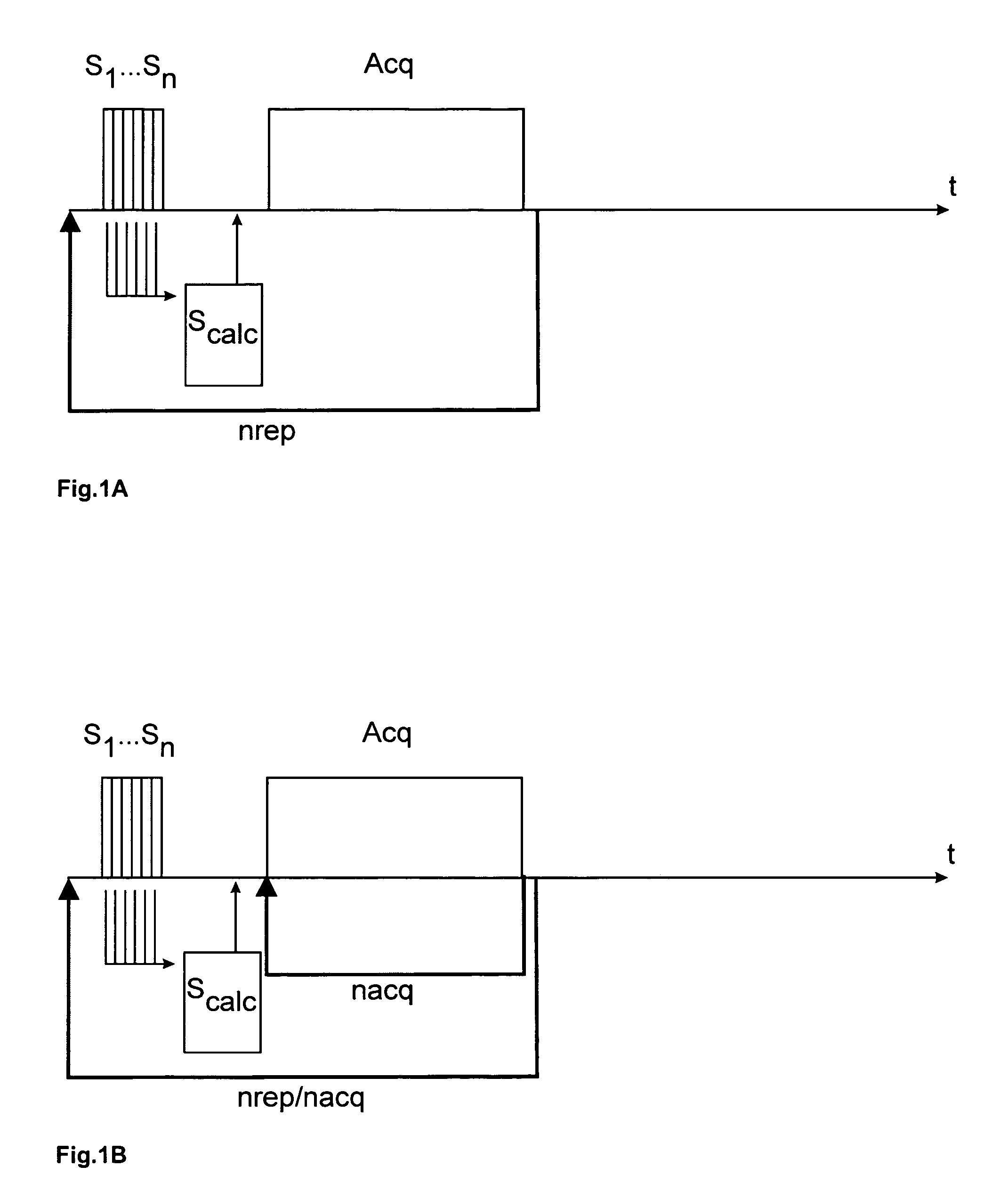
[0030]FIG. 1A shows a diagram of the method for dynamic adjustment of the magnetic field distribution with nrep times repeated data acquisition, wherein before each individual measurement Acq the magnetic field distribution is measured in n acquisition steps S1 . . . Sn of a shim sequence and the shim currents required for compensation of field inhomogeneities are calculated and applied in the subsequent calculation step Scalc.

[0031]The acquisition steps S1 . . . Sn of the additionally inserted periodic shim sequence may be based on navigator measurements according to the FASTMAP method. Towards this end, at least one measurement (for the previous application for a one-time static field measurement typically also several measurements) is carried out in each of the three main directions of the magnetic field. The number n of measuring steps is therefore typically n≧3.

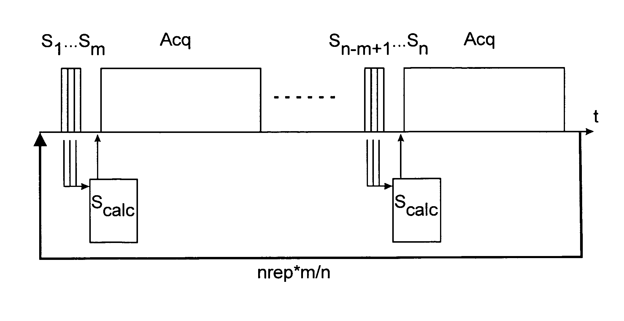
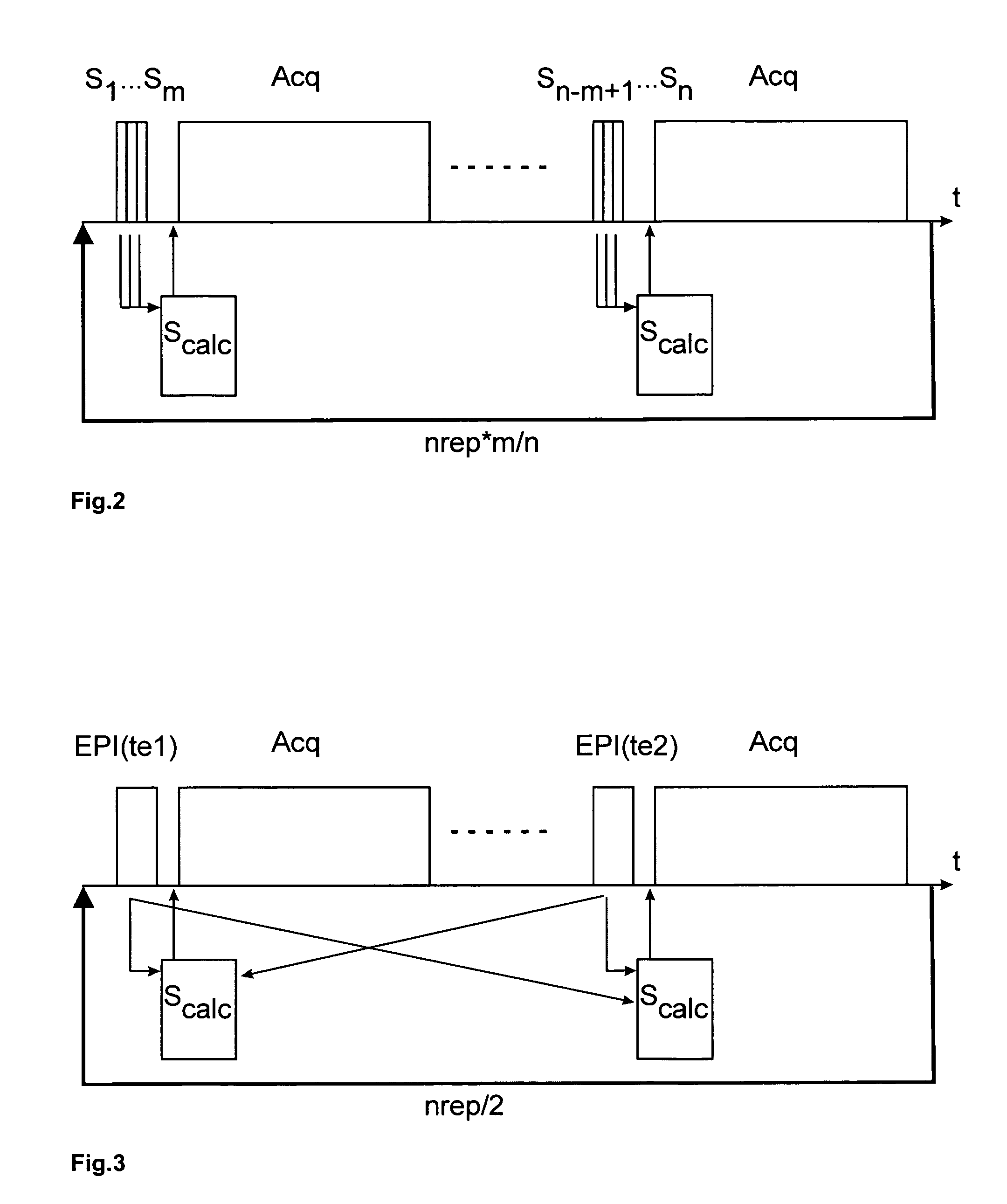
[0032]In a modification of this approach, measurement and compensation of the magnetic field distribution is not perfo...


PUM


Abstract

A magnetic resonance (NMR) method for fast, dynamic, spatially resolved measurement of the temporal changes in NMR signals by means of repeated data acquisition in individual measurements (Acq) with measuring sequences which are sensitive to a parameter to be observed, in an NMR apparatus with shim coils for correcting the magnetic field is characterized in that during data acquisition of each individual measurement (Acq) in acquisition steps (S1 . . . Sn) with a time lag, the magnetic field distribution in the NMR apparatus is measured, technically or physiologically based changes in the magnetic field distribution are determined therefrom in a calculation step (Scalc) as well as a change in the currents in the magnetic field required for compensation thereof, and the dynamic changes in the magnetic field distribution are compensated for by means of the correspondingly changed shim currents. The inventive method permits dynamic detection of the changes in the magnetic field distribution through the above-mentioned factors during the measurement and compensation thereof through corresponding re-calculation of Δy(x,y,z) or ΔB0(x,y,z) and adjustment of the shim currents to render the magnetic field distribution for subsequent measurements again preferably identical to the initial magnetic field distribution.

Description

[0001]The invention concerns a magnetic resonance (NMR) method for rapid, dynamic, spatially resolved measurement of the temporal changes in NMR signals by means of repeated data acquisition in individual measurements with measuring sequences which are sensitive to a parameter to be observed, in an NMR apparatus with shim coils which correct the magnetic field.[0002]The methods generally used today for NMR imaging utilize spatially varying magnetic fields for spatial encoding of the observed spins. These magnetic fields which are used for spatial encoding overlap the basic field of the outer magnet due to temporally varying magnetic field gradients. A two- or three-dimensional data set is generated through acquisition of the temporally varying nuclear resonance signal, and is converted into corresponding spatial images by means of corresponding multi-dimensional Fourier transformation. A spatially true image is obtained only if the basic field in the observed volume is constant and ...

Claims


Application Information

Patent Timeline
Patent Type & Authority Patents(United States)
IPC IPC(8): G01V3/00
CPCG01R33/3875
Inventor HENNIG, JUERGENSPECK, OLIVERZAITSE, MAXIM
Owner UNIVERSITATSKLINIKUM FREIBURG
Why Eureka
Try Eureka