Camera, aperture controlling method and apparatus, lens controlling method and apparatus, and edging amount controlling method and apparatus

a technology of aperture control and lens control, applied in the field of camera, aperture lens edging amount control method and apparatus, can solve the problems of poor photometry capability at a low brightness, easy vibration of the camera, and deterioration of the image quality of the movie display for confirming a view angle, so as to reduce the resolution and reduce the image quality of the optical system. , the effect of lowering the resolution

Inactive Publication Date: 2007-11-06
FUJIFILM CORP
View PDF10 Cites 33 Cited by
  • Summary
  • Abstract
  • Description
  • Claims
  • Application Information

AI Technical Summary

Benefits of technology

[0032]If the focal length of the taking lens is at the telephoto side, vibrations, for example by hands, easily occurs. However, if an image is taken in the low resolution mode, such vibrations are not obvious. Therefore, an amount of blur in the image caused by the vibrations is calculated and the result of the calculation is compared with the image quality data in an extra aperture. If the amount of blur by vibrations is larger than the image quality data in the extra aperture, the shutter speed is accelerated by using the extra aperture size so as to take the image at a point where the vibrations and the image quality are balanced.
[0033]A contour intensity is preferably controlled so that lowering of the resolution due to a lowered image quality of the optical system is supplemented and that an edging is stricter with respect to the image signal.

Problems solved by technology

However, in an automatic exposure adjustment (AE), because noise compositions are amplified by gaining up and performing photometry if the brightness of the subject is too low, many errors occur, and photometry capability at a low brightness is poor.
Other problems concerning the conventional camera are that: the camera easily vibrates when using an electronic zoom, an image quality of a movie display for confirming a view angle is deteriorated with respect to the subject with a low brightness, observability of the movie display is poor due to a smear phenomenon which occurs in taking of the subject with extreme brightness, and so forth.

Method used


Image

  • Camera, aperture controlling method and apparatus, lens controlling method and apparatus, and edging amount controlling method and apparatus
  • Camera, aperture controlling method and apparatus, lens controlling method and apparatus, and edging amount controlling method and apparatus
  • Camera, aperture controlling method and apparatus, lens controlling method and apparatus, and edging amount controlling method and apparatus

Examples


embodiment 1

Alternative Embodiment 1

[0136]FIGS. 16 and 17 are views showing an outer appearance of a camera 70 and FIG. 18 is a block diagram of the camera 70 in the alternative embodiments of the present invention. The parts which are similar or the same as those of the camera 10 are assigned the same reference numbers, and the description on them is omitted.

[0137]A wide conversion lens 72 can be attached to the top end of the barrel of the camera 70 in FIG. 16. Moreover, the camera 70 has the mode dial 13, and the photometry sensor 15 comprising an AF illuminating part 15A and an AF light receiving part 15B is disposed at the front face of the camera. An active sensor is used in the present embodiment, but the photometry sensor is not limited to that; sensors such as a phase contrast sensor of a passive format may be used.

[0138]The mode dial 13 is a means for selecting operation modes of the camera. Modes such as a set up mode, a successive taking mode, a manual taking mode, an automatic taki...

embodiment 2

Alternative Embodiment 2

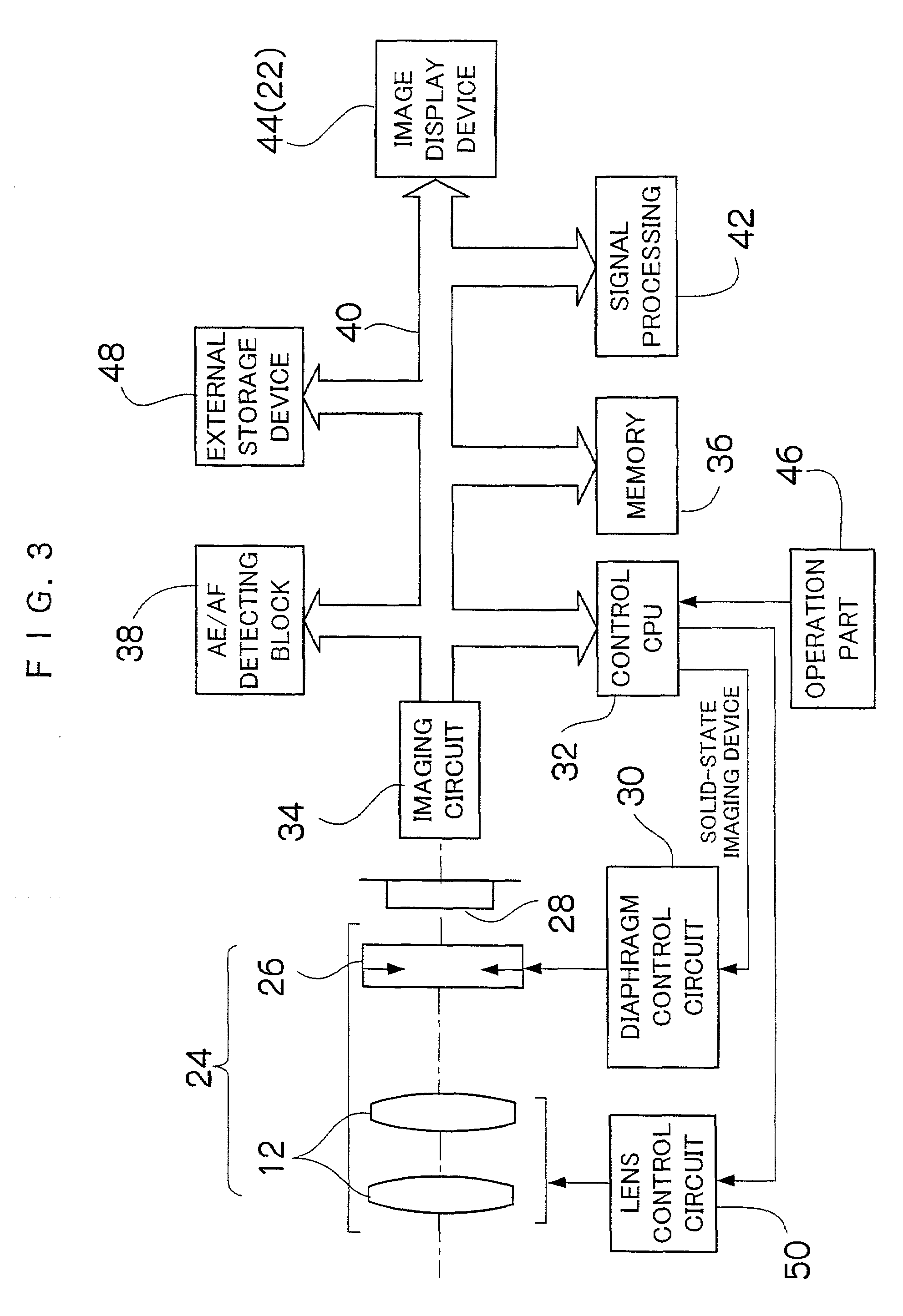
[0153]Next, another alternative embodiment of the present invention will be described. FIG. 20 is a block diagram of a camera 90 of the present embodiment. The same or similar parts as those in FIG. 3 are assigned the same reference numbers and the description on them is omitted.

[0154]A taking system (the taking lens 12) of the camera 90 in FIG. 20 has a zoom lens 91 and a focus lens 92. A lens group 91A and a lens group 91B move along an optical axis while a positional relationship between the two lens groups 91A and 91B is regulated by the cam mechanism (not shown) in order to change a focal length. A zoom control circuit 94 controls driving of the zoom lens 91 in accordance with an instruction from the control CPU 32. The focus lens 92 contributes to focus adjustment. A focus control circuit 95 controls driving of the focus lens 92 in accordance with an instruction from the CPU 32.

[0155]A signal from the operation part such as the release switch 18 and the...

embodiment 3

Alternative Embodiment 3

[0162]FIGS. 21 and 22 show an embodiment for use at outside the range which secures the capability with respect to the focus position (focus), but there is also am embodiment for use at outside the range which secures the capability with respect to the focal length (zoom). FIGS. 23 and 24 show the relationship between the focal length and the lens capability.

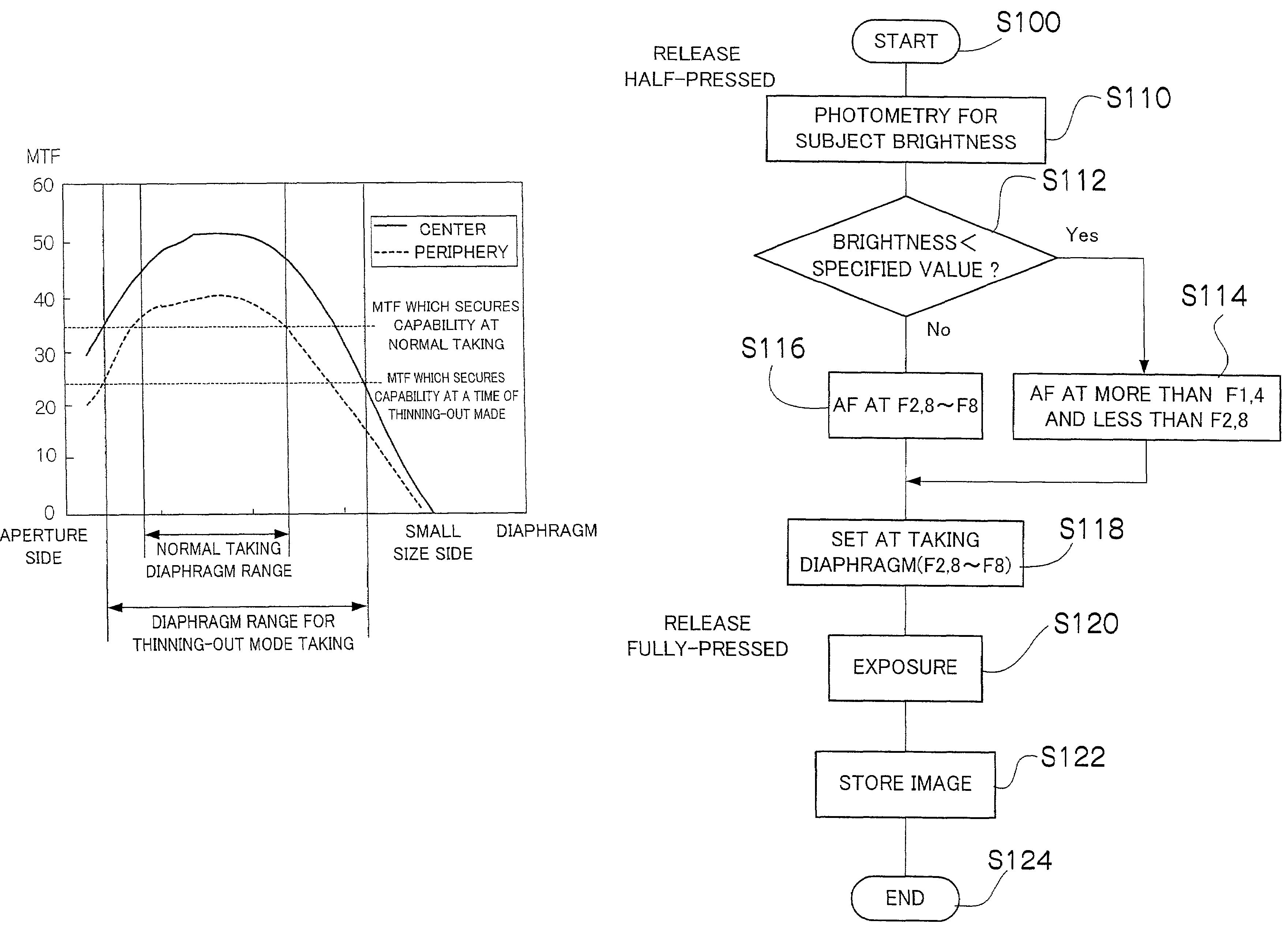
[0163]FIG. 23 shows a graph of a relationship between the focal length and the MTF (when taking under low resolution). As seen from FIG. 23, an area where the MTF at the center and the periphery is 35% or more in the normal taking is the level which secures the capability, by which the regulation at a telephoto side is decided; in short, a focal length changeable range (zoom range) in the normal taking is regulated as shown in (4).

[0164]In the low resolution, however, the taken image is not affected despite the MTF being lowered down to 20%, so the taking at a side which is still closer to the telephoto s...


PUM


Abstract

Maximum and minimum aperture sizes are regulated with regard to a diaphragm in order to secure predetermined optical capability in an optical unit which includes a taking lens and the diaphragm. In a normal taking, the diaphragm is used within a normal taking range from the maximum to the minimum aperture sizes. In the present invention, an aperture size which is larger than the maximum size and a size which is smaller than the minimum size (extra aperture size or extra small size) are respectively set at outside the range that secures the capability. The aperture sizes of the diaphragm at outside the specified range are used at least for one of the following: automatic exposure (AE) adjustment, auto focus (AF) adjustment, electronic zoom, displaying a moving image, taking for recording the moving image, and taking under a low resolution by thinning out pixels.

Description

BACKGROUND OF THE INVENTION[0001]1. Field of the Invention[0002]The present invention relates to a camera such as a digital camera, a video camera and a silver-halide camera, an aperture controlling method, an aperture controlling apparatus, a lens controlling method, a lens controlling apparatus, an edging amount controlling method and an edging amount controlling apparatus which are applied to an optical system of the camera.[0003]2. Description of the Related Art[0004]In a conventional art, an operatable range of a lens is restricted with regard to a diaphragm for a camera, a point-blank limit, and a zoom limit, in order to secure a predetermined optical capability (e.g. an imaging capability) of the lens. Concerning the diaphragm for example, a maximum and a minimum aperture sizes are so specified as to control the diaphragm within the operatable range. Japanese Patent Application Laid-open No. 5-53170 discloses changing a diaphragm corresponding with a zoom position and correct...

Claims


Application Information

Patent Timeline
Patent Type & Authority Patents(United States)
IPC IPC(8): H04N5/238H04N5/232H04N5/235G03B7/00G03B7/095G02B7/02G02B7/04G02B7/28G03B5/00G03B7/17G03B9/02G03B9/07G03B15/05G03B19/02H04N101/00
CPCH04N23/673H04N23/667H04N23/63H04N23/69H04N23/72H04N23/71H04N23/75
Inventor YAMAZAKI, AKIHISAMISAWA, ATSUSHIKONDO, SHIGERUNAKAZAWA, MICHITAKA
Owner FUJIFILM CORP
Why Eureka
Try Eureka