Lens optical system
a technology of optical system and lens, applied in the field of lens optical system, can solve the problems of optical system designed for white light, one that needs, wavelength-dependent diffraction efficiency of diffraction grating, etc., and achieve the effect of wide wavelength range and high diffraction efficiency
- Summary
- Abstract
- Description
- Claims
- Application Information
AI Technical Summary
Benefits of technology
Problems solved by technology
Method used
Image

Examples
embodiments 1 to 4
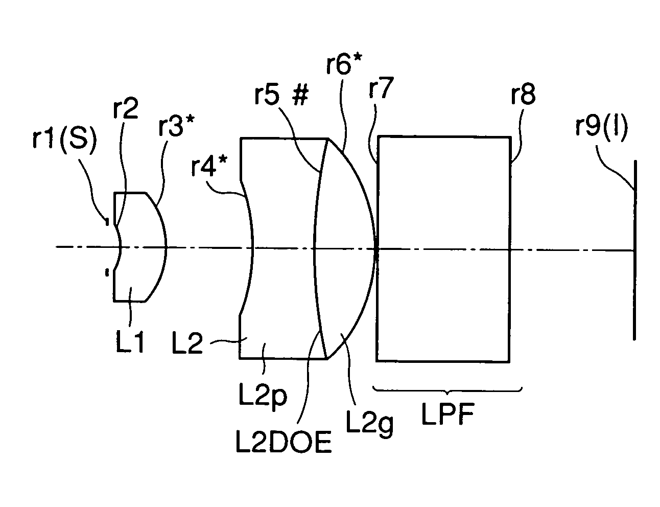
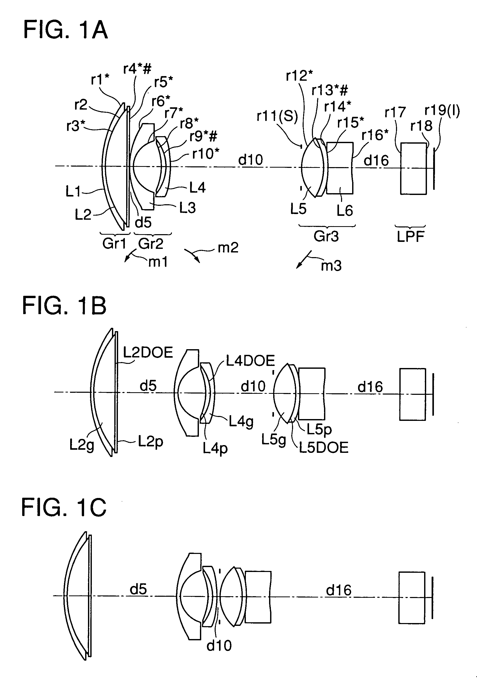
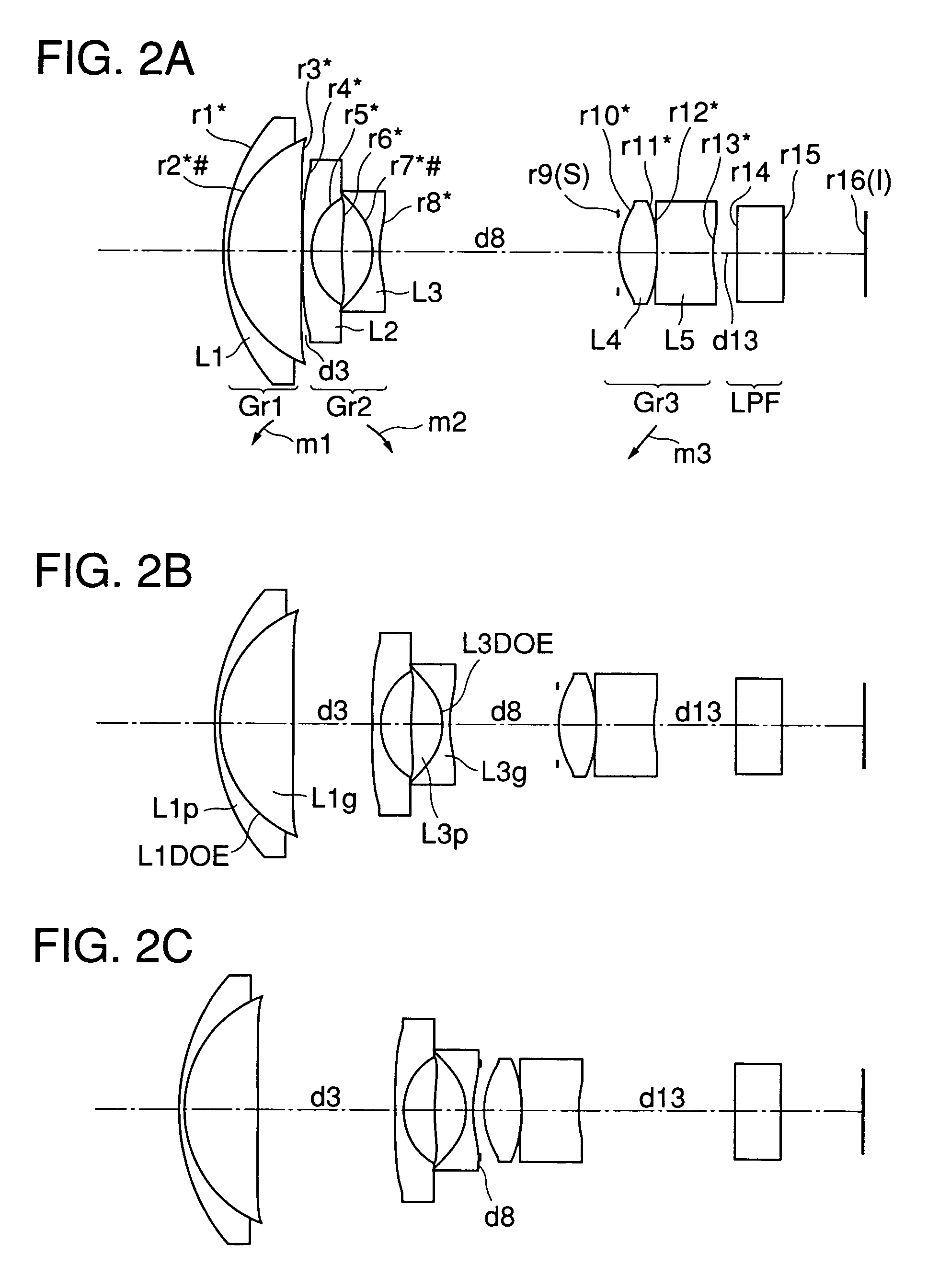
[0063]The lens optical system of the first embodiment (FIGS. 1A to 1C) is composed of a first lens unit (Gr1) having a lens element (L1) and a cemented lens element (L2), a second lens unit (Gr2) having a lens element (L3) and a cemented lens element (L4), a third lens unit (Gr3) having an aperture stop (S), a cemented lens element (L5), and a lens element (L6), and a low-pass filter (LPF). The lens optical system of the second embodiment (FIGS. 2A to 2C) is composed of a first lens unit (Gr1) having a cemented lens element (L1), a second lens unit (Gr2) having a lens element (L2) and a cemented lens element (L3), a third lens unit (Gr3) having an aperture stop (S) and two lens elements (L4 and L5), and a low-pass filter (LPF). The lens optical system of the third embodiment (FIGS. 3A to 3C) is composed of a first lens unit (Gr1) having a lens element (L1) and a cemented lens element (L2), a second lens unit (Gr2) having an aperture stop (S) and a cemented lens element (L3), and a l...
examples 1 to 4
[0080]Hereinafter, examples of lens optical systems embodying the present invention will be presented with reference to their construction data, graphic representations of aberrations, and other data. Tables 1 to 4 list the construction data of Examples 1 to 4, which respectively correspond to the first to fourth embodiments described above and have lens arrangements as shown in FIGS. 1A to 1C, 2A to 2C, 3A to 3C, and 4. Moreover, Table 5 lists the construction data of an example taken up for comparison (Comparison Example 1), which corresponds to Example 1 and others and has a lens arrangement as shown in FIGS. 5A to 5C.
[0081]In the construction data of each example, ri (i=1, 2, 3, . . . ) represents the radius of curvature of the ith surface counted from the object side, di (i=1, 2, 3, . . . ) represents the ith axial distance counted from the object side, and Ni (i=1, 2, 3, . . . ) and vi (i=1, 2, 3, . . . ) respectively represent the refractive index for the d line and the Abbe ...
embodiment 5
[0096]The lens optical system of the fifth embodiment is built as a three-unit zoom lens system that is composed of, from the object side, a first lens unit (Gr1) having a negative optical power, a second lens unit (Gr2) having a positive optical power, and a third lens unit (Gr3) having a positive optical power, wherein zooming is performed by varying the distance between the first and second lens units (Gr1 and Gr2) and so forth. In this lens optical system, between the second and third lens units (Gr2 and Gr3), an aperture stop (S) is disposed that is kept in a fixed position together with the third lens unit (Gr3) during zooming. Moreover, a low-pass filter (LPF) is disposed at the image-plane (I) side end of the lens optical system.
[0097]In the lens optical system of the fifth embodiment (FIGS. 12A to 12C), the lens units are each composed, from the object side, as follows. The first lens unit (Gr1) is composed of a negative biconcave lens element and a positive meniscus lens e...
PUM
 Abstract
Description
Claims
Application Information
 - Generate Ideas
- Intellectual Property
- Life Sciences
- Materials
- Tech Scout
- Unparalleled Data Quality
- Higher Quality Content
- 60% Fewer Hallucinations
Browse by: Latest US Patents, China's latest patents, Technical Efficacy Thesaurus, Application Domain, Technology Topic, Popular Technical Reports.
© 2025 PatSnap. All rights reserved.Legal|Privacy policy|Modern Slavery Act Transparency Statement|Sitemap|About US| Contact US: help@patsnap.com