
Autofocus barcode scanner and the like employing micro-fluidic lens

a microfluidic lens and barcode scanner technology, applied in the field of optoelectronic reading devices, can solve the problems of incompatibility with many other imaging applications, limited increase, and blurring of pupil diffraction, so as to reduce or eliminate the need for illumination, reduce the f-number, and wide spatial resolution range

Active Publication Date: 2007-11-20
INTERMEC IP
View PDF11 Cites 114 Cited by
  • Summary
  • Abstract
  • Description
  • Claims
  • Application Information

AI Technical Summary

Benefits of technology

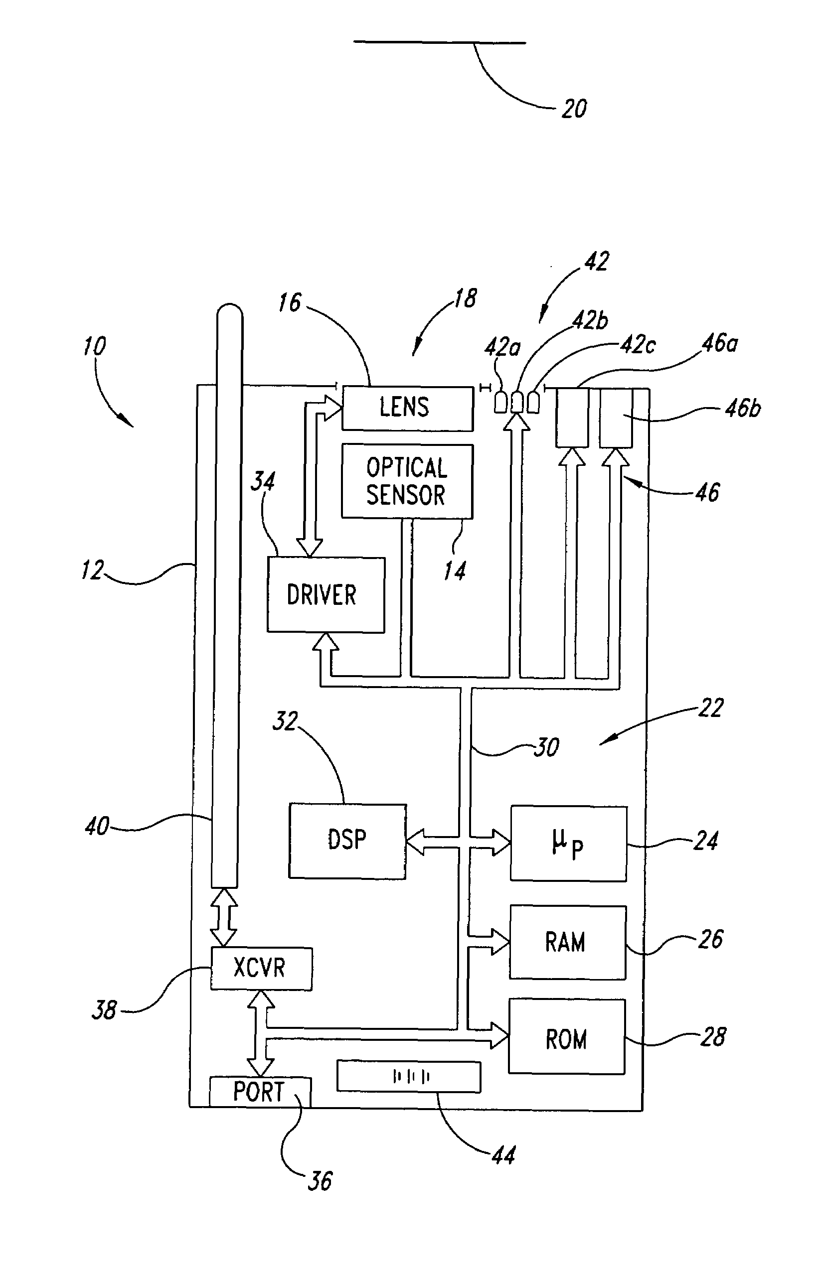
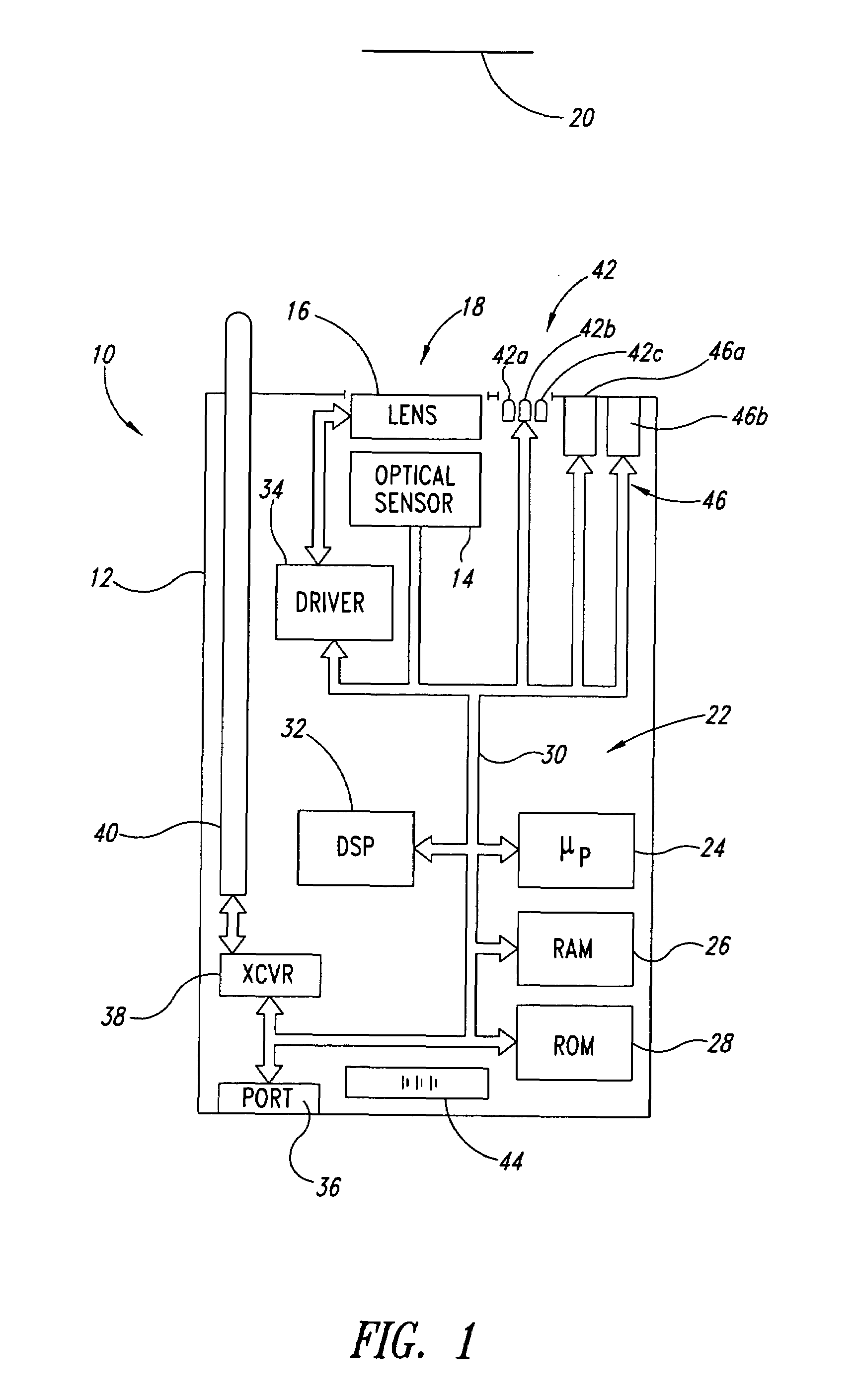
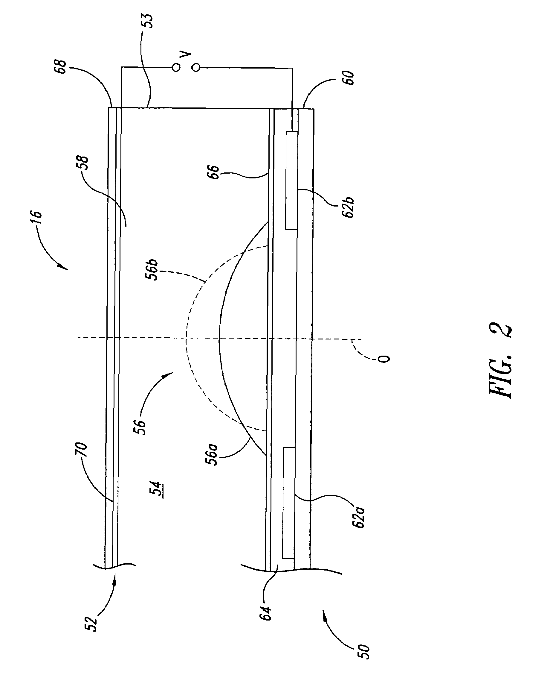
The patent describes a machine-readable symbol reader that uses a microfluidic lens to capture images of targets carrying machine-readable symbols. The reader includes an optical sensor and a controller to adjust the focal length of the lens. The reader can also have an illumination system to improve image quality, and a range finder system to determine the distance between the reader and the target. The method of operating the reader involves acquiring an image, determining the focus value of the lens, adjusting the lens to a second focal length, and iterating through a series of increments to determine the best focus length. The auto-focus system eliminates the need for mechanical elements, providing a faster and more reliable system. It also allows for polychromatic operation and reduces the need for illumination.

Problems solved by technology

The increase is limited by the minimum illumination required by the sensor, and ultimately the pupil diffraction blurring.
Additionally, while fixed focus barcode readers are cost effective, they are highly specialized devices, typically having a short range and limited to monochromatic uses, and thus incompatible with many other imaging applications.
Moving lens systems disadvantageously require relatively large and precise mechanical lenses, tracks, linkages and drives.
Moving lens systems are also rather slow in responding, making such systems impractical for most automatic “on-fly” barcode reading.
Additionally, the thickness of the crystal film reduces the optical transmission, limiting the auto-focus range.

Method used


Image

  • Autofocus barcode scanner and the like employing micro-fluidic lens
  • Autofocus barcode scanner and the like employing micro-fluidic lens
  • Autofocus barcode scanner and the like employing micro-fluidic lens

Examples


Embodiment Construction

[0035]In the following description, certain specific details are set forth in order to provide a thorough understanding of various embodiments of the invention. However, one skilled in the art will understand that the invention may be practiced without these details. In other instances, well-known structures associated with optoelectronic reading devices including light sources, lens, optical sensors, processors, memories, and communications devices have not been shown or described in detail to avoid unnecessarily obscuring descriptions of the embodiments of the invention.

[0036]Unless the context requires otherwise, throughout the specification and claims which follow, the word “comprise” and variations thereof, such as, “comprises” and “comprising” are to be construed in an open, inclusive sense, that is as “including but not limited to.” The headings provided herein are for convenience only and do not interpret the scope or meaning of the claimed invention.

[0037]Reference througho...


PUM


Abstract

A machine-readable symbol reader includes a microfluidic lens assembly providing responsive, reliable auto-focus functionality. A range finder may provide distance to a planar target (e.g., barcode symbol) information for use in auto-focusing, with or without localization. Illumination system, if included, is selectively controlled based on the distance to target and auto-focusing functionality to substantially reduce power consumption. The localization may color optical sensors.

Description

CROSS-REFERENCE TO RELATED APPLICATION[0001]This application claims the benefit under 35 U.S.C. § 119(e) of U.S. Provisional Patent Application No. 60 / 538,868 filed Jan. 23, 2004, where this provisional application is incorporated herein by reference in its entirety.BACKGROUND OF THE INVENTION[0002]1. Field of the Invention[0003]This disclosure generally relates to optoelectronic reading devices for acquiring images of machine-readable symbols, such as bar code, area code, matrix or stacked code symbols, and particularly to providing autofocus capability in such devices.[0004]2. Description of the Related Art[0005]Optoelectronic readers for reading bar codes and other machine-readable symbols fall into two general groups: 1) moving beam devices commonly referred to as scanners (e.g., laser scanners), and 2) fixed beam devices commonly referred to as imagers (e.g., CCD imagers). Each group has its own relative advantages.[0006]Moving beam devices typically move or scan a light across...

Claims


Application Information

Patent Timeline
Patent Type & Authority Patents(United States)
IPC IPC(8): G03B3/10G02B3/14G02B26/02G06K7/10
CPCG02B3/14G02B26/005G06K7/10801G06K7/10702G06K2007/10485
Inventor MASSIEU, JEAN-LOUIS
Owner INTERMEC IP
Learn More