Autofocus barcode scanner and the like employing micro-fluidic lens

a microfluidic lens and barcode scanner technology, applied in the field of optoelectronic reading devices, can solve the problems of incompatibility with many other imaging applications, limited increase, and blurring of pupil diffraction, so as to reduce or eliminate the need for illumination, reduce the f-number, and wide spatial resolution range

Active Publication Date: 2005-10-06
INTERMEC IP
View PDF10 Cites 136 Cited by
  • Summary
  • Abstract
  • Description
  • Claims
  • Application Information

AI Technical Summary

Benefits of technology

[0016] Eliminating mechanical elements from the auto-focus assembly, may provide a responsive (i.e., quick) and / or reliable auto-focus system that provides a wide spatial resolution range (“focus adaptiveness”) for a machine-readable symbol reader. Focus adaptiveness, eliminates depth-of-field as a critical issue, thus, allowing the f-number to be significantly reduced. The best resolution of the lens is not achieved for a fixed best focus distance, but rather can be tuned between short and far field (cut-off frequency f=1 / (λ*f−number)). The system may reduce or eliminate the need for illumination, reducing the overall cost of the reader, as well as reducing operating cost, and / or extending operating time between charging for battery operated readers.
[0017] Because the sensor illumination increases in direct proportionality to the square of the f-number, the illumination system may be eliminated or at least reduced. If illumination is still required, for example, for dark environments, the illumination power can be closed-loop controlled along with the electronic gain and / or the integration time of the sensor, as part of an automatic gain strategy. In most cases, ambient illumination provides enough illumination to significantly enhance autonomy for mobile applications.
[0018] The auto-focus system may also be compatible with color image sensors, allowing polychromatic operation. Ambient light and most barcode contrasts are polychromatic, so color sensors can be used without loss of spatial resolution. More generally, auto-focus permits barcode applications to coexist with other color image applications having variable object distances.

Problems solved by technology

The increase is limited by the minimum illumination required by the sensor, and ultimately the pupil diffraction blurring.
Additionally, while fixed focus barcode readers are cost effective, they are highly specialized devices, typically having a short range and limited to monochromatic uses, and thus incompatible with many other imaging applications.
Moving lens systems disadvantageously require relatively large and precise mechanical lenses, tracks, linkages and drives.
Moving lens systems are also rather slow in responding, making such systems impractical for most automatic “on-fly” barcode reading.
Additionally, the thickness of the crystal film reduces the optical transmission, limiting the auto-focus range.

Method used


Image

  • Autofocus barcode scanner and the like employing micro-fluidic lens
  • Autofocus barcode scanner and the like employing micro-fluidic lens
  • Autofocus barcode scanner and the like employing micro-fluidic lens

Examples


Embodiment Construction

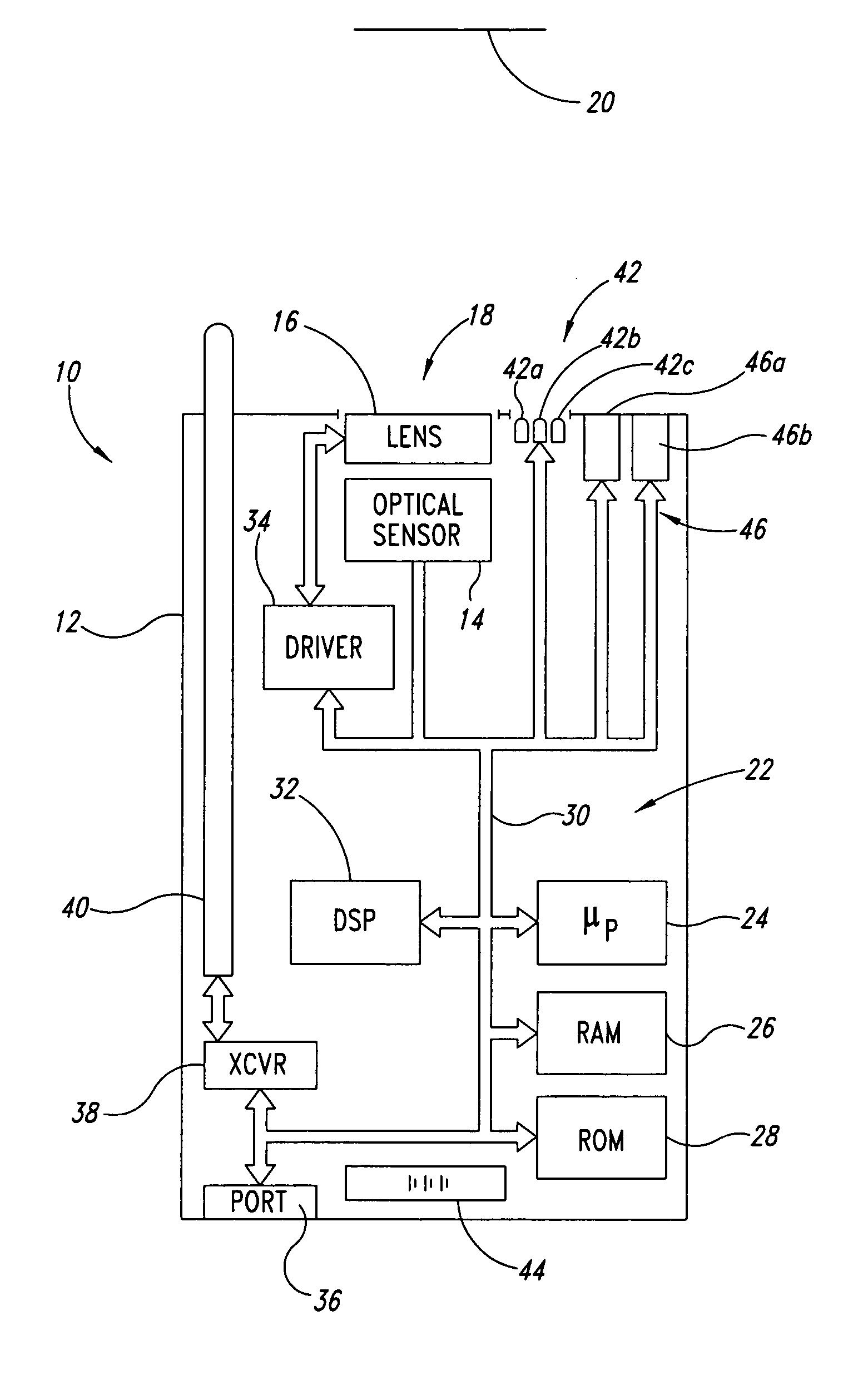
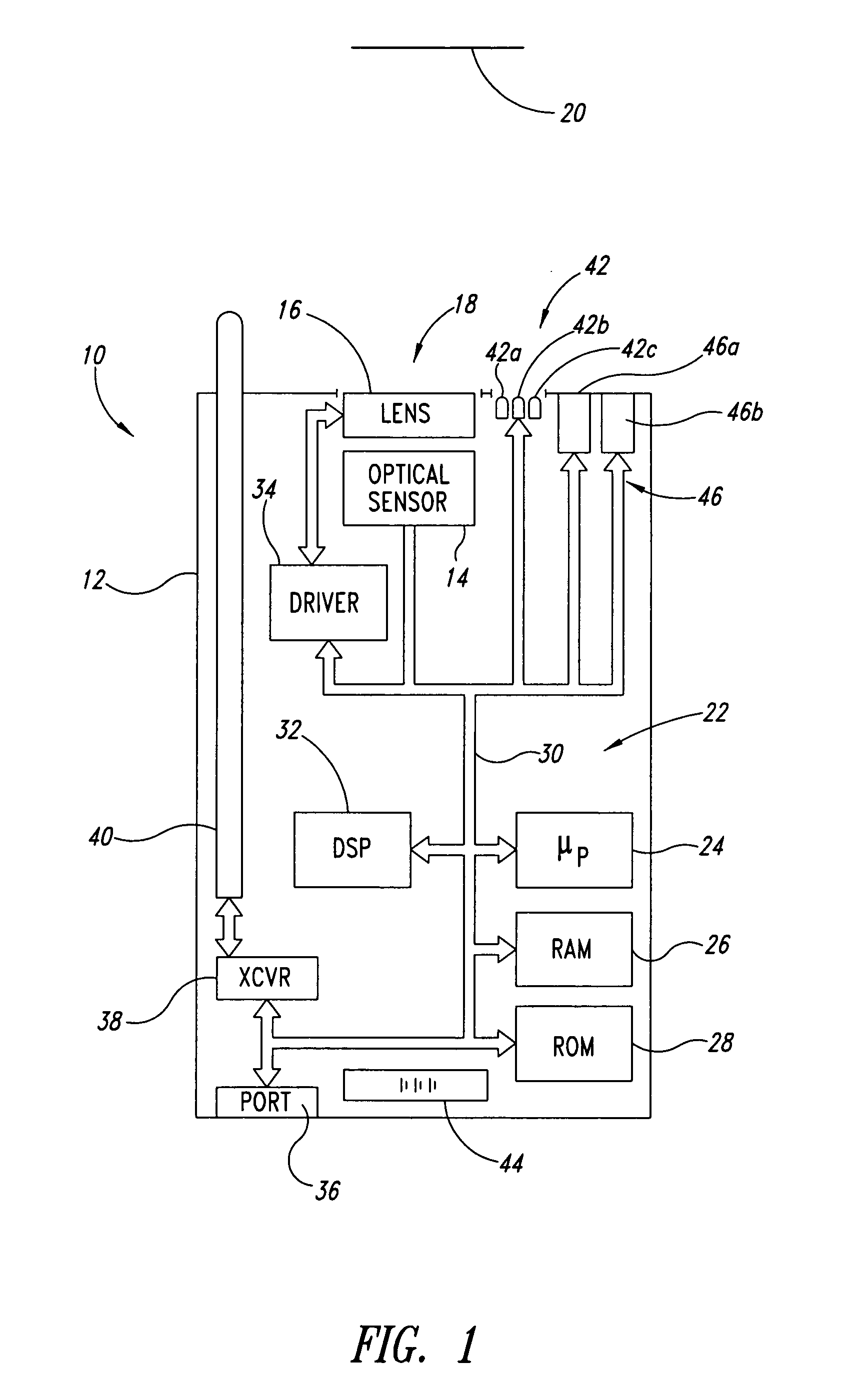
[0033] In the following description, certain specific details are set forth in order to provide a thorough understanding of various embodiments of the invention. However, one skilled in the art will understand that the invention may be practiced without these details. In other instances, well-known structures associated with optoelectronic reading devices including light sources, lens, optical sensors, processors, memories, and communications devices have not been shown or described in detail to avoid unnecessarily obscuring descriptions of the embodiments of the invention.

[0034] Unless the context requires otherwise, throughout the specification and claims which follow, the word “comprise” and variations thereof, such as, “comprises” and “comprising” are to be construed in an open, inclusive sense, that is as “including but not limited to.” The headings provided herein are for convenience only and do not interpret the scope or meaning of the claimed invention.

[0035] Reference thr...


PUM


Abstract

A machine-readable symbol reader includes a microfluidic lens assembly providing responsive, reliable auto-focus functionality. A range finder may provide distance to a planar target (e.g., barcode symbol) information for use in auto-focusing, with or without localization. Illumination system, if included, is selectively controlled based on the distance to target and auto-focusing functionality to substantially reduce power consumption. The localization may color optical sensors.

Description

BACKGROUND OF THE INVENTION [0001] 1. Field of the Invention [0002] This disclosure generally relates to optoelectronic reading devices for acquiring images of machine-readable symbols, such as bar code, area code, matrix or stacked code symbols, and particularly to providing autofocus capability in such devices. [0003] 2. Description of the Related Art [0004] Optoelectronic readers for reading bar codes and other machine-readable symbols fall into two general groups: 1) moving beam devices commonly referred to as scanners (e.g., laser scanners), and 2) fixed beam devices commonly referred to as imagers (e.g., CCD imagers). Each group has its own relative advantages. [0005] Moving beam devices typically move or scan a light across a target. For example, a scanner may employ a laser diode and a mechanism for moving a laser beam across the target. While it may be possible to move the light source itself, scanners typically employ one or more rotating or oscillating mirrors which refle...

Claims


Application Information

Patent Timeline
Patent Type & Authority Applications(United States)
IPC IPC(8): G02B3/14G02B26/02G03B3/10G06K7/10
CPCG02B3/14G02B26/005G06K2007/10485G06K7/10801G06K7/10702
Inventor MASSIEU, JEAN-LOUIS
Owner INTERMEC IP
Why Eureka
Try Eureka